

In accordance with Article 3 of the Treaty on the Eurasian Economic Commission of 18 November 2011, the Council of the Eurasian Economic Commission has decided:
1. To adopt the attached Technical Regulation of the Customs Union "On Safety of Equipment Operating under Excess Pressure" (TR CU 032/2013).
2. To establish that:
a) the Technical Regulation of the Customs Union "On Safety of Equipment Operating under Excess Pressure" (TR CU 032/2013) (hereinafter, the Technical Regulation) enters into force on 1 February 2014;
b) until 31 December 2028, the territory of the Russian Federation permits the establishment and application of mandatory requirements for certain types of products specified in subparagraphs "a" – "j" (except for piping), "l" and "n" of paragraph 2 of the Technical Regulation. This applies to products produced (manufactured) in the territories of states that are not Member States of the Eurasian Economic Union and imported into the territory of the Russian Federation. The territory of the Russian Federation also permits conformity assessment of such products in accordance with the regulatory legal acts of the Government of the Russian Federation.
The placing on the market of the products specified in the first paragraph of this subparagraph is permitted provided that their safety is ensured, and only in the territory of the Russian Federation. For these products, the documents on conformity assessment provided for by the Technical Regulation may not be issued. Information that the products are placed on the market and may circulate only in the territory of the Russian Federation is stated in the passport of such products. It is also stated in the document on conformity assessment against the mandatory requirements established in accordance with the first paragraph of this subparagraph.
The products specified in the first paragraph of this subparagraph are not marked with the single mark of product circulation on the market of the Eurasian Economic Union.
The exercise of rights of ownership, use and (or) disposal of the products specified in the first paragraph of this subparagraph is not permitted in the territories of the Member States of the Eurasian Economic Union, except for the Russian Federation.
Footnote. Paragraph 2 as amended by Decision of the Council of the Eurasian Economic Commission No. 107 of 26.09.2025 (enters into force upon expiry of 30 calendar days from the date of its official publication).3. This Decision enters into force upon expiry of 30 calendar days from the date of its official publication.
Members of the Council of the Eurasian Economic Commission:
For the Republic of Belarus | For the Republic of Kazakhstan | For the Russian Federation |
S. Rumas | K. Kelimbetov | I. Shuvalov |
ADOPTED
by Decision of the Council
of the Eurasian Economic Commission
No. 41 of 2 July 2013
TECHNICAL REGULATION
of the Customs Union "On Safety of Equipment Operating under Excess Pressure" (TR CU 032/2013)
This Technical Regulation establishes uniform safety requirements for equipment operating under excess pressure that is placed on the market and intended for use in the customs territory of the Eurasian Economic Union (hereinafter, the Union) (hereinafter, equipment). These requirements are mandatory for application and compliance in the customs territory of the Union.
If other Technical Regulations of the Union (Customs Union) that establish requirements for the equipment have been adopted, the equipment must also comply with the requirements of those Technical Regulations of the Union (Customs Union).
Footnote. Preamble as amended by Decision of the Council of the Eurasian Economic Commission No. 49 of 23.04.2021 (enters into force upon expiry of 180 calendar days from the date of its official publication).I. Scope of Application
1. This Technical Regulation establishes safety requirements for equipment during development (design) and manufacture (production), as well as requirements for the marking of equipment, for the purposes of protecting human life and health and property, and preventing actions that mislead consumers.
2. This Technical Regulation applies to the following types of equipment:
a) vessels intended for compressed, liquefied, and dissolved under pressure gases and vapours, used for Group 1 fluids and having:
a design pressure above 0,05 MPa, a volume of more than 0,001 m3, and a product of the maximum allowable working pressure value and the volume value exceeding 0,0025 MPa · m3;
a design pressure above 20 MPa and a volume above 0,0001m3 up to and including 0,001 m3.
The categories of vessels intended for gases and used for Group 1 fluids are given in Table 1 of Annex No. 1 to this Technical Regulation;
b) vessels intended for compressed, liquefied, and dissolved under pressure gases and vapours, used for Group 2 fluids and having:
a design pressure above 0,05 MPa, a volume of more than 0,001 m3, and a product of the maximum allowable working pressure value and the volume value exceeding 0,005 MPa · m3;
a design pressure above 100 MPa and a volume above 0,0001m3 up to and including 0,001 m3.
The categories of vessels intended for gases and used for Group 2 fluids are given in Table 2 of Annex No. 1 to this Technical Regulation;
c) vessels intended for liquids, used for Group 1 fluids and having:
a design pressure above 0,05 MPa, a volume of more than 0,001 m3, and a product of the maximum allowable working pressure value and the volume value exceeding 0,02 MPa · m3;
a design pressure above 50 MPa and a volume above 0,0001 m3 up to and including 0,001 m3 .
The categories of vessels intended for liquids and used for Group 1 fluids are given in Table 3 of Annex No. 1 to this Technical Regulation;
d) vessels intended for liquids, used for Group 2 fluids and having:
a design pressure above 1 MPa, a volume of more than 0,01 m3, and a product of the maximum allowable working pressure value and the volume value exceeding 1 MPa · m3;
a design pressure above 100 MPa and a volume above 0,0001m3 up to and including 0,01 m3 .
The categories of vessels intended for liquids and used for Group 2 fluids are given in Table 4 of Annex No. 1 to this Technical Regulation;
e) boilers with a volume of more than 0,002 m3, intended for producing hot water with a temperature above 110 0C, or steam with an excess pressure above 0,05 MPa, as well as fired vessels
with a volume of more than 0,002 m3.
The categories of steam boilers, hot-water boilers and fired vessels are given in Table 5 of Annex No. 1 to this Technical Regulation;
f) piping and valves with a design pressure above 0,05 MPa and a nominal diameter of more than 25 mm, intended for compressed, liquefied, and dissolved under pressure gases and vapours, and used for Group 1 fluids.
The categories of piping and valves intended for compressed, liquefied, and dissolved under pressure gases and vapours, and used for Group 1 fluids, are given in Table 6 of Annex No. 1 to this Technical Regulation;
g) piping and valves with a design pressure above 0,05 MPa, a nominal diameter of more than 32 mm, and a product of the design pressure value and the nominal diameter value exceeding 100 MPa·mm, intended for compressed, liquefied, and dissolved under pressure gases and vapours, and used for Group 2 fluids.
The categories of piping and valves intended for compressed, liquefied, and dissolved under pressure gases and vapours, and used for Group 2 fluids, are given in Table 7 of Annex No. 1 to this Technical Regulation;
h) piping and valves with a design pressure above 0,05 MPa, a nominal diameter of more than 25 mm, and a product of the design pressure value and the nominal diameter value exceeding 200 MPa·mm, intended for liquids and used for Group 1 fluids.
The categories of piping and valves intended for liquids and used for Group 1 fluids are given in Table 8 of Annex No. 1 to this Technical Regulation;
i) piping and valves with a design pressure above 1 MPa, a nominal diameter of more than 200 mm, and a product of the design pressure value and the nominal diameter value exceeding 500 MPa·mm, intended for liquids and used for Group 2 fluids.
The categories of piping and valves intended for liquids and used for Group 2 fluids are given in Table 9 of Annex No. 1 to this Technical Regulation;
j) equipment elements (assembly units) and component parts thereof that withstand pressure above 0,05 MPa;
k) deleted by Decision of the Council of the Eurasian Economic Commission No. 49 of 23.04.2021 (enters into force upon expiry of 180 calendar days from the date of its official publication).l) indicating devices and safety devices, except for devices classified as measuring instruments;
m) pressure chambers (except single-occupant medical pressure chambers);
n) safety devices and instruments.
Footnote. Paragraph 2 as amended by Decision of the Council of the Eurasian Economic Commission No. 49 of 23.04.2021 (enters into force upon expiry of 180 calendar days from the date of its official publication).3. This Technical Regulation does not apply to the following products:
a) trunk pipelines, in-field pipelines and local distribution pipelines intended for the transportation of gas, oil and other products, except for equipment used at pressure regulating stations or at compressor stations;
b) gas distribution networks and gas consumption networks;
c) equipment specially designed for use in the field of nuclear power engineering, and equipment operating with a radioactive medium;
d) vessels operating under pressure generated by an explosion inside them in accordance with the technological process, or by combustion in the mode of self-propagating high-temperature synthesis;
e) equipment specially designed for use on sea and river vessels and other floating craft, and on underwater facilities;
f) brake equipment of railway rolling stock, motor vehicles and other means of transport;
g) vessels specially designed for use
on aeroplanes and other aircraft;
h) defence equipment;
i) machine parts that are not independent vessels (pump or turbine casings, cylinders of steam, hydraulic and internal combustion engines, air machines and compressors);
j) single-occupant medical pressure chambers;
k) equipment with aerosol dispensers;
l) enclosures of high-voltage electrical equipment (switchgear, switching mechanisms, transformers and rotating electrical machines);
m) enclosures and casings of elements of electric power transmission systems (power supply cable products and communication cables) operating under excess pressure;
n) equipment manufactured (produced) from a non-metallic flexible (elastic) shell;
o) exhaust or intake gas silencers;
p) containers or siphons for carbonated beverages.
q) networks for the supply, distribution and discharge of water with a temperature of 110 °C or less, as well as supply conduits in hydropower installations and the associated fittings;
r) heating appliances and piping in water heating systems of buildings and structures;
s) equipment and equipment elements for supplying engines with gaseous fuel (compressed natural gas, liquefied petroleum gas (or liquefied hydrocarbon gas), liquefied natural gas, fuel-grade dimethyl ether) specially designed for use on wheeled vehicles, self-propelled machines, and agricultural and forestry tractors;
t) piping support and hanger systems and their elements.
Footnote. Paragraph 3 as amended by Decisions of the Council of the Eurasian Economic Commission No. 49 of 23.04.2021 (enters into force upon expiry of 180 calendar days from the date of its official publication); No. 137 of 24.11.2023 (enters into force upon expiry of 360 calendar days from the date of its official publication).II. Basic Terms
4. For the purposes of applying this Technical Regulation, the terms established by the Protocol on Technical Regulation within the Eurasian Economic Union (Annex No. 9 to the Treaty on the Eurasian Economic Union of 29 May 2014) and by the model conformity assessment schemes approved by Decision of the Council of the Eurasian Economic Commission No. 44 of 18 April 2018 are used, as well as terms with the following meanings:
"valves" – a technical device installed on piping and on tubular elements of boilers and vessels, intended to control the flow of the working medium (shut-off, prevention of backflow, regulation, distribution, mixing, separation), including by changing the flow cross-section;
"cylinder" – a vessel with 1 or 2 necks for fitting valves, flanges or nozzles, intended for the transport, storage and use of compressed, liquefied or dissolved gases under pressure;
"pressure chamber" – a vessel in which reduced and (or) increased pressure is created, which is equipped with instruments and equipment, and which can accommodate people;
"drum" – a vessel of cylindrical or other shape that can be rolled from one place to another and stood on its ends without additional supports, and that is intended for the transport and storage of liquid and other substances;
"commissioning" – a documented event that records the readiness of equipment for application (use);
"volume" – the volume of the internal cavity of equipment, determined from the nominal dimensions specified in the drawings;
"working medium group" – a set of working media divided into:
group 1, comprising working media that consist of flammable, oxidising (except air with an oxygen content corresponding to the natural composition of atmospheric air), combustible, explosive, toxic and highly toxic gases, liquids and vapours in a single-phase state, and their mixtures;
group 2, comprising all other working media not assigned to group 1;
"internal pressure", "external pressure" – excess pressure acting on the internal or external surfaces of the equipment wall;
"test pressure" – excess pressure at which the strength and tightness test of equipment is performed;
"operating pressure" – the maximum excess pressure that arises during the normal course of the working process;
"design pressure" – the pressure for which the strength calculation of equipment is performed;
"nominal pressure (PN)" – design pressure at a temperature of 20 °C, used in the strength calculation of equipment (valves, piping parts and connections, etc.);
"nominal diameter (DN)" – a parameter used for piping systems and valves as a characteristic of connecting parts. The nominal diameter is approximately equal to the internal diameter of the connected piping, expressed in millimetres and corresponding to the nearest value from the series of numbers adopted in the established procedure. It is stated without units of measurement;
"equipment identification" – a procedure that establishes the identity of the characteristics of equipment with the features provided for this equipment (type or group of equipment) by this Technical Regulation and by the documents specified in paragraphs 16 and 45 of this Technical Regulation, and with the features specified in the information on the equipment, and that ensures the equipment can be unambiguously classified as an object of technical regulation of this Technical Regulation;
"waste-heat boiler" – a boiler that uses the heat of hot exhaust gases released during technological processes, during engine operation, or during additional combustion of process products and (or) supplementary fuel;
"energy-technological boiler" – a steam or hot-water boiler (including a soda recovery boiler) in whose furnace technological materials are processed;
"electrode boiler" – a steam or hot-water boiler that uses the heat released when electric current flows through water;
"electrically heated boiler" – a steam or hot-water boiler that uses the heat released by electric heating elements;
"hot-water boiler" – a device intended for heating water that is under pressure above atmospheric and is used as a heat carrier outside this device;
"steam boiler" – a device intended for generating steam at a pressure above atmospheric, which is used outside this device;
"limit state of equipment" – the state of equipment in which its further operation is not permissible;
"intended use" – use of equipment in accordance with its purpose and with the technical characteristics specified in the manufacturer's technical documentation;
"series production" – a type of production characterised by the manufacture of homogeneous products according to standard design solutions and (or) by the use of standard technological processes associated with unchanging types of equipment, including in assembly operations, for the manufacture (production) of constantly recurring equipment parts regardless of the types of their subsequent assembly;
"equipment repair" – restoration of equipment elements that are damaged, worn or have become unusable for any reason, bringing the equipment back to operable condition;
"assigned operating life" – the total operating time upon reaching which the operation of equipment shall be terminated regardless of its technical condition;
"vessel" – a hermetically sealed container (stationary or mobile) intended for chemical, thermal and other technological processes, and for the storage and transport of gaseous, liquid and other substances;
"fired vessel" – a vessel in which the working medium, under pressure above atmospheric, receives heat from the flame and combustion products through a wall that separates them;
"assigned service life" – the calendar duration of equipment operation upon reaching which operation shall be terminated regardless of its technical condition;
"design service life" – the service life in calendar years established during design and counted from the date of commissioning of the equipment;
"working medium temperature" – the minimum (maximum) temperature of the medium during the normal course of the technological process;
"design wall temperature" – the temperature at which the physical and mechanical properties and the allowable stress of the material are determined and the strength calculation of equipment elements is performed;
"allowable wall temperature" – the maximum (minimum) wall temperature at which operation of the equipment is permitted;
"piping" – equipment intended for transporting various media under excess pressure, consisting of valves, pipes, flanges and other piping parts and elements joined together by permanent and (or) detachable joints, as well as the parts of the support and hanger system attached to them that ensure the safe operation of the piping. The boundaries of the piping are determined by the design documentation;
"safety relief devices" – devices intended to protect vessels, boilers and piping from failure when the allowable values of pressure or temperature are exceeded;
"life cycle" – the period of time from the release of equipment by the manufacturer until its disposal;
"tank" – a mobile vessel permanently mounted on the frame of a railway platform, on the chassis of a motor vehicle (trailer), including road tankers, or on other means of transport, intended for the transport and storage of gaseous, liquid and other substances;
"operation of equipment" – the stage of the life cycle from the commissioning of equipment until its disposal;
"equipment element" – an assembly unit of equipment intended to perform one of its main functions.
Footnote. Paragraph 4 as amended by Decision of the Council of the Eurasian Economic Commission of 23.04.2021 No. 49 (enters into force upon expiry of 180 calendar days from the date of its official publication).III. Rules of Circulation on the Market of the Union
Footnote. The heading of Section III as amended by Decision of the Council of the Eurasian Economic Commission of 23.04.2021 No. 49 (enters into force upon expiry of 180 calendar days from the date of its official publication).
5. Equipment is placed on the market of the Union if it complies with the requirements of this Technical Regulation and of other Technical Regulations of the Union (Customs Union) that apply to this equipment, and provided that it has undergone conformity assessment in accordance with Section VI of this Technical Regulation and with other Technical Regulations of the Union (Customs Union) that apply to it.
Footnote. Paragraph 5 - as worded by Decision of the Council of the Eurasian Economic Commission of 23.04.2021 No. 49 (enters into force upon expiry of 180 calendar days from the date of its official publication).6. Equipment whose conformity with the requirements of this Technical Regulation has not been confirmed shall not be marked with the single mark of product circulation on the market of the Union and shall not be permitted for placing on the market.
Footnote. Paragraph 6 as amended by Decision of the Council of the Eurasian Economic Commission of 23.04.2021 No. 49 (enters into force upon expiry of 180 calendar days from the date of its official publication).IV. Ensuring the Safety of Equipment during Development (Design) and Manufacture (Production)
7. Equipment shall be developed (designed) and manufactured (produced) in such a way that its compliance with safety requirements is ensured during intended use, operation and maintenance.
8. In order to determine the risks for equipment, factors representing the following main types of hazard shall be taken into account:
a) presence of unprotected moving elements;
b) vibration;
c) presence of elements posing an explosion and fire hazard;
d) impermissible deviations of parameters of the structure, assembly units and safety devices that affect safety;
e) fire, natural and man-made emergencies;
f) overheating;
g) excess of pressure (the pressure exceeds the operating or design pressure specified in the operational documentation);
h) damage associated with the deposition of working medium impurities on the internal surfaces of equipment elements;
i) corrosion and other types of wear of the material of equipment elements;
j) malfunction of safety devices and safety systems;
k) cessation of operation of auxiliary equipment;
l) extinction of flames in the furnace during chamber combustion of fuel;
m) loss of voltage on all instrumentation and control devices and on remote and automatic control devices;
n) drop of the liquid working medium level below the minimum allowable level;
o) rise of the liquid working medium level above the maximum allowable level;
p) reduction of the heat transfer medium flow rate through the equipment below the minimum allowable value;
q) reduction of the heat transfer medium pressure in the equipment below the minimum allowable value;
r) rise of the heat transfer medium temperature at the equipment outlet to the limit value specified by the manufacturer;
s) failure of direct-reading liquid working medium level indicators.
Footnote. Paragraph 8 as amended by Decision of the Council of the Eurasian Economic Commission No. 49 of 23.04.2021 (enters into force upon expiry of 180 calendar days from the date of its official publication).9. During the development (design) of equipment and its elements, hazardous factors shall be identified and taken into account. An acceptable level of risk during development (design) is ensured by means of a strength calculation and compliance with a set of technical requirements, using experimental or expert methods or on the basis of operating data for similar equipment.
Footnote. Paragraph 9 as worded by Decision of the Council of the Eurasian Economic Commission No. 49 of 23.04.2021 (enters into force upon expiry of 180 calendar days from the date of its official publication).10. Depending on the volume or nominal diameter, as well as on the maximum allowable working pressure, equipment is classified into categories (1st, 2nd, 3rd and 4th) in accordance with Annex No. 1 to this Technical Regulation.
11. The safety of equipment is ensured by compliance, during development (design) and manufacture (production), with the safety requirements set out in this section and in Annex No. 2 to this Technical Regulation.
The set of documents justifying the safety of equipment, taking into account all hazard factors and safety requirements specific to it, includes:
terms of reference, technical specifications (TU) or other documents establishing requirements for the equipment at the stages of development (design) and production (manufacture);
design documentation (drawings, diagrams, specifications, calculations);
technical documentation accompanying the equipment;
test reporting documents (test reports, conclusions, reports, certificates);
other documents containing an assessment of risk and operational reliability (if any).
For boilers, vessels and piping developed (designed) using standards that establish specific safety requirements for equipment and are included in the list of standards whose voluntary application ensures compliance with the requirements of this Technical Regulation, the documents justifying safety are the strength calculation and the related requirements of the standards included in that list.
For equipment developed (designed) without the use of standards that establish specific safety requirements for equipment and are included in the list of standards whose voluntary application ensures compliance with the requirements of this Technical Regulation, the set of documents justifying safety shall be supplemented by a document confirming that the technical solutions adopted ensure a level of equipment safety not lower than the level established by the standards included in that list.
Footnote. Paragraph 11 as amended by Decision of the Council of the Eurasian Economic Commission No. 49 of 23.04.2021 (enters into force upon expiry of 180 calendar days from the date of its official publication).12. During the manufacture (production) of equipment and safety devices, the manufacturer shall ensure their compliance with the parameters and characteristics established by the design documentation and with the requirements of this Technical Regulation.
13. The manufacturer shall carry out the equipment tests provided for by the design documentation.
14. Deviations from the design documentation during the manufacture (production) of equipment shall be agreed with the developer (designer).
15. Equipment shall be safe throughout its entire service life, provided that the consumer implements the measures to ensure its safety established in the technical documentation.
16. The technical documentation accompanying the equipment includes:
a) the equipment passport or documents ensuring the identification of elements (assembly units, parts) and component parts;
b) deleted by Decision of the Council of the Eurasian Economic Commission No. 49 of 23.04.2021 (enters into force upon expiry of 180 calendar days from the date of its official publication).c) an assembly drawing or a drawing showing the main dimensions (for valves, piping parts and flanges, a sketch showing the main dimensions is permitted);
d) passports of safety devices (where provided for by the design documentation);
e) flow capacity calculation of safety devices (where provided for by the design documentation);
f) strength calculation of the equipment (for valves, piping parts and flanges, an extract from the calculation is permitted);
g) operating manual (instructions) (except for elements (assembly units, parts) of equipment and component parts);
h) drawings, diagrams, calculations and other documentation in accordance with the supply agreement (contract).
Footnote. Paragraph 16 as amended by Decision of the Council of the Eurasian Economic Commission No. 49 of 23.04.2021 (enters into force upon expiry of 180 calendar days from the date of its official publication).161. Technical documentation drawn up in a foreign language shall be accompanied by a translation into Russian and (or), where the legislation of a Member State of the Union (hereinafter – the Member State) contains a corresponding requirement, into the state language of the Member State.
Footnote. The Technical Regulation was supplemented with paragraph 161 in accordance with Decision of the Council of the Eurasian Economic Commission No. 49 of 23.04.2021 (enters into force upon expiry of 180 calendar days from the date of its official publication).17. The equipment passport is the main document for equipment identification.
An equipment passport is mandatory for the circulation of equipment in the customs territory of the Union at all stages of the equipment life cycle.
The equipment passport is issued by the manufacturer.
The equipment passport shall bear the signature of the manufacturer's responsible person and the manufacturer's seal (if the legislation of the Member State requires a legal entity or an individual registered as a sole proprietor to have a seal), and shall state the date of its issue.
Footnote. Paragraph 17 as amended by Decision of the Council of the Eurasian Economic Commission No. 49 of 23.04.2021 (enters into force upon expiry of 180 calendar days from the date of its official publication).18. Depending on the type of equipment, the equipment passport shall contain information in accordance with paragraphs 19 – 23 of this Technical Regulation.
19. The piping passport includes the following information:
a) names and addresses of the operating organisation and of the piping manufacturer;
b) name and category of the piping;
c) date of manufacture (production);
d) name and group of the working medium;
e) design pressure, MPa (kgf/cm2), operating pressure, MPa (kgf/cm2), design wall temperature, °C, operating temperature of the working medium, °C;
f) design service life;
g) design operating life;
h) design number of start-ups;
i) diagrams, drawings, certificates and other documents for the manufacture (production) and installation of the piping.
Footnote. Paragraph 19 as amended by Decision of the Council of the Eurasian Economic Commission No. 49 of 23.04.2021 (enters into force upon expiry of 180 calendar days from the date of its official publication).20. The boiler passport includes the following information (the scope of information is determined by the manufacturer depending on the boiler type):
a) general information:
name and address of the manufacturer;
date of manufacture (production);
type (model);
name and purpose;
factory number;
design service life;
design operating life of the boiler and its main parts;
design number of start-ups;
geometric dimensions of the boiler;
b) technical characteristics and parameters:
design fuel type and its calorific value, MJ/m3 (kcal/m3) or MJ/kg (kcal/kg);
fuel consumption, m3/h (t/h);
type and characteristics of the furnace unit (burners);
design, operating and test pressure, MPa (kgf/cm2);
maximum allowable hydraulic resistance of the boiler at rated output, MPa (kgf/cm2);
minimum allowable pressure at rated temperature, MPa (kgf/cm2);
rated steam temperature at the boiler outlet, 0C;
design temperature of superheated steam (liquid),0C;
rated liquid temperature at the boiler inlet, 0C;
rated and maximum liquid temperature at the boiler outlet, 0C;
rated, minimum and maximum allowable steam output, t/h;
rated, minimum and maximum heat output, kW;
heating surface of the boiler and its main parts, m2;
volume, m3;
minimum and maximum allowable liquid flow rate, m3/h;
c) information on safety devices (including type, number, installation location, cross-sectional area, nominal diameter, steam or liquid discharge coefficient, value (range) of the start-to-open pressure);
d) information on liquid (water) level indicators (including indicator type, number, installation location);
d) information on the main valves (including quantity, nominal diameter, nominal pressure, operating parameters, body material, installation location);
e) information on the main equipment for measurement, control, signalling, regulation and automatic protection (including quantity, type (make));
f) information on pumps (including type, quantity, operating parameters, drive type);
g) information on the main boiler elements manufactured (produced) from sheet steel (information on quantity, dimensions, material, welding and heat treatment, results of measurement inspection and non-destructive testing, tests of permanent joints, hydraulic (pneumatic) tests, etc.);
h) information on the boiler elements manufactured (produced) from pipes (including quantity, dimensions, material, welding and heat treatment, information on the results of measurement inspection and non-destructive testing, tests of permanent joints, hydraulic (pneumatic) tests, etc.);
i) information on nozzles, covers, heads, reducers and flanges (including quantity, dimensions, material);
j) information on the heat transfer medium (including name, maximum allowable application temperature, auto-ignition temperature in open space, solidification temperature, boiling temperature, change (curve) of the boiling temperature as a function of pressure, other data affecting safe operation);
k) drawings, diagrams and engineering drawings of the boiler and its main elements, and other documents (summary sheet of factory modifications, completeness list, specification stating the main dimensions of assembly units, etc.);
l) other information ensuring the safe operation of the boiler.
Footnote. Paragraph 20 as amended by Decision of the Council of the Eurasian Economic Commission No. 49 of 23.04.2021 (enters into force upon expiry of 180 calendar days from the date of its official publication).21. The vessel passport includes the following information:
a) general information:
name and address of the manufacturer;
name of the vessel;
date of manufacture (production);
factory number;
design service life;
allowable number of loading cycles, where the stress amplitude values can be determined;
b) information on technical characteristics and parameters:
operating, design and test pressure, MPa (kgf/cm2);
operating temperature of the working medium, 0C;
design wall temperature, 0C;
minimum allowable vessel wall temperature at design pressure, °C;
name of the working medium;
working medium group;
corrosion (erosion) allowance, mm;
volume, m3;
mass of the empty vessel, kg;
maximum mass of the filled medium, kg;
c) information on the main parts (information on their quantity, dimensions, information on materials, welding (brazing) and heat treatment), results of measurement inspection and non-destructive testing, tests of permanent joints, hydraulic (pneumatic) tests, etc.);
d) information on nozzles, flanges, covers and fasteners (including quantity, dimensions, material);
e) information on safety devices, main valves, instrumentation and control devices, and safety instruments (including quantity, nominal diameter, nominal pressure and (or) design pressure, body material, installation location);
f) drawings, diagrams and engineering drawings of the vessel, and other documents (summary sheet of factory modifications, completeness list, specification stating the main dimensions of assembly units, etc.);
g) start-up (shutdown) procedure under sub-zero temperature conditions and other information ensuring the safe operation of the vessel (if such other information exists).
Footnote. Paragraph 21 as amended by Decision of the Council of the Eurasian Economic Commission No. 49 of 23.04.2021 (enters into force upon expiry of 180 calendar days from the date of its official publication).22. The cylinder passport includes the following information:
a) general information:
name and address of the manufacturer;
date of manufacture (production);
cylinder designation;
name and group of the working medium;
factory number;
b) information on technical characteristics and parameters:
operating pressure, MPa (kgf/cm2);
test pressure, MPa (kgf/cm2);
main dimensions of the cylinder, cylinder drawing;
volume, l;
mass, kg;
neck thread;
neck sealing;
operating temperature range, 0C;
maximum number of fillings;
design service life from the date of manufacture (production), years;
c) requirements for transportation and storage of the cylinder;
d) requirements for installation of the cylinder;
e) requirements for operation of the cylinder;
f) other information ensuring the safe operation of the cylinder.
Footnote. Paragraph 22 as amended by Decision of the Council of the Eurasian Economic Commission No. 49 of 23.04.2021 (enters into force upon expiry of 180 calendar days from the date of its official publication).23. The valve passport includes the following information:
a) general information:
name and address of the manufacturer;
date of manufacture (production);
name, designation and identification (factory) number;
purpose of the valves;
information on conformity confirmation;
b) information on technical parameters:
nominal diameter (DN);
nominal pressure (PN) or operating pressure (Pp), MPa (kgf/cm2);
name and group of the working medium;
working medium temperature, 0C;
seat tightness;
climatic version and ambient parameters;
type of connection to the piping;
hydraulic characteristics (resistance coefficient, or nominal flow capacity, or flow coefficient);
resistance to external influences (where this information must be stated);
mass, kg;
reliability indicators;
safety indicators;
type of actuator and its main technical characteristics;
c) information on the materials of the main parts;
d) other information ensuring the safe operation of the valves.
Footnote. Paragraph 23 as amended by Decision of the Council of the Eurasian Economic Commission No. 49 of 23.04.2021 (enters into force upon expiry of 180 calendar days from the date of its official publication).24. The manufacturer may supplement the information specified in paragraphs 19 – 23 of this Technical Regulation with information reflecting the design features of the specific equipment.
25. Repealed by Decision of the Council of the Eurasian Economic Commission No. 49 of 23.04.2021 (enters into force upon expiry of 180 calendar days from the date of its official publication).26. The equipment manufacturer shall provide the equipment with an operating manual (instructions).
The operating manual (instructions) is prepared at the development (design) stage of the equipment.
27. The operating manual (instructions) includes:
a) information on the design, operating principle and characteristics (properties) of the equipment;
b) instructions for installation or assembly, commissioning adjustment or regulation, maintenance and repair of the equipment;
c) instructions for use of the equipment and the safety measures to be observed during operation of the equipment (including commissioning, intended use, maintenance, all types of repair, periodic diagnostics, testing, transportation, packaging, preservation and storage conditions);
d) assigned indicators (assigned storage life, assigned service life and (or) assigned operating life), depending on the design features.
Upon expiry of the assigned indicators (assigned storage life, assigned service life and (or) assigned operating life) specified in the operating manual (instructions), operation of the equipment is terminated and a decision is made to send it for repair, to dispose of it, or to inspect it and establish new assigned indicators (assigned operating life, storage life, service life);
e) a list of critical failures and possible erroneous actions of personnel that lead to an incident or accident;
f) actions of personnel in the event of an incident, critical failure or accident;
g) limit state criteria;
h) instructions for decommissioning and disposal;
i) information on the qualifications of the operating personnel;
j) name, location and contact information of the manufacturer (person authorised by the manufacturer) and the importer.
28. The operating manual (instructions) is drawn up in Russian and, where required by the legislation of the Member States, in the state languages of the Member States.
The operating manual (instructions) is issued on paper; a set of operational documents on electronic media may also be attached. For non-household equipment, at the manufacturer's choice, the operating manual (instructions) may be supplied with the equipment on electronic media only.
Footnote. Paragraph 28 as amended by Decision of the Council of the Eurasian Economic Commission No. 49 of 23.04.2021 (enters into force upon expiry of 180 calendar days from the date of its official publication).29. Marking shall be applied to the equipment in the form of clear and indelible lettering containing the following information:
a) name and (or) designation of the type, make and model of the equipment;
b) parameters and characteristics affecting safety;
c) name of the material from which the equipment (elements) is manufactured (produced);
d) name of the manufacturer and its trademark (if any);
e) factory number;
f) date of manufacture (production).
Footnote. Paragraph 29 as amended by Decision of the Council of the Eurasian Economic Commission No. 49 of 23.04.2021 (enters into force upon expiry of 180 calendar days from the date of its official publication).30. The location of the marking is determined by the design organisation and is stated in the operating manual (instructions).
If the information specified in paragraph 29 of this Technical Regulation cannot be applied directly to the equipment, it may be stated only in the operating manual (instructions) supplied with this equipment.
31. Equipment intended for the transport of gases (cylinders and road tankers) shall bear distinctive colouring and identification information in accordance with the requirements set out in Annex No. 3 to this Technical Regulation. Where such equipment is coated (clad) with corrosion-resistant and thermal insulation materials, the colouring need not be applied along the entire length.
Footnote. Paragraph 31 as amended by Decision of the Council of the Eurasian Economic Commission No. 49 of 23.04.2021 (enters into force upon expiry of 180 calendar days from the date of its official publication).32. Equipment elements and components shall be marked in accordance with the supply agreement (contract). The marking shall ensure their identification.
33. The technical documentation for the equipment shall be kept by the manufacturer (person authorised by the manufacturer) for the design service life from the date on which production of this equipment ceases.
Footnote. Paragraph 33 as amended by Decision of the Council of the Eurasian Economic Commission No. 49 of 23.04.2021 (enters into force upon expiry of 180 calendar days from the date of its official publication).34. The rules for the operation of equipment are established by the legislation of the Member States.
V. Ensuring conformity with safety requirements
35. Conformity of equipment with the requirements of this Technical Regulation is ensured by direct fulfilment of these requirements or by fulfilment of the requirements of the standards included in the list of standards whose voluntary application ensures compliance with the requirements of this Technical Regulation.
36. The methods of research (testing) and measurement of equipment are established by the standards included in the list of standards containing the rules and methods of research (testing) and measurement, including sampling rules, that are necessary for the application and fulfilment of the requirements of this Technical Regulation and for the conformity assessment (confirmation) of equipment.
VI. Conformity Assessment (Confirmation) of Equipment
37. Equipment placed on the market in the customs territory of the Union is subject to conformity assessment (confirmation) against the requirements of this Technical Regulation.
Footnote. Paragraph 37 as amended by Decision of the Council of the Eurasian Economic Commission No. 49 of 23.04.2021 (enters into force upon expiry of 180 calendar days from the date of its official publication).38. Conformity assessment (confirmation) of equipment against the requirements of this Technical Regulation is carried out in the form of state control (supervision) and in the form of conformity confirmation.
39. State control (supervision) of compliance with the requirements of this Technical Regulation is carried out in accordance with the legislation of the Member States.
40. Conformity confirmation of equipment against the requirements of this Technical Regulation (hereinafter – conformity confirmation) is carried out by:
a) certification by an accredited certification body (conformity assessment (confirmation) body) included in the Unified Register of Conformity Assessment Bodies of the Union (hereinafter – certification body);
b) declaration of conformity procedure on the basis of the applicant's own evidence and (or) evidence obtained with the participation of a certification body or an accredited testing laboratory (centre) included in the Unified Register of Conformity Assessment Bodies of the Union (hereinafter – accredited testing laboratory).
Footnote. Paragraph 40 as amended by Decision of the Council of the Eurasian Economic Commission No. 49 of 23.04.2021 (enters into force upon expiry of 180 calendar days from the date of its official publication).41. Conformity confirmation is carried out according to the certification schemes and declaration schemes established by this Technical Regulation.
42. The declaration of conformity procedure for equipment against the requirements of this Technical Regulation is carried out by the applicant in respect of equipment and equipment elements of the 1st and 2nd categories, as well as equipment of any category whose manufacture or final manufacture using permanent joints is carried out at the place of operation.
Footnote. Paragraph 42 as amended by Decision of the Council of the Eurasian Economic Commission No. 49 of 23.04.2021 (enters into force upon expiry of 180 calendar days from the date of its official publication).43. Certification is carried out in respect of equipment and equipment elements of the 3rd and 4th categories.
Footnote. Paragraph 43 as amended by Decision of the Council of the Eurasian Economic Commission No. 49 of 23.04.2021 (enters into force upon expiry of 180 calendar days from the date of its official publication).44. The only document confirming conformity of equipment with the requirements of this Technical Regulation is either the declaration of conformity or the certificate of conformity.
45. When conformity confirmation is carried out, the applicant compiles a set of documents for the equipment, which includes:
a) safety justification;
b) equipment passport;
c) operating manual (instructions);
d) design documentation;
e) results of strength calculations and flow capacity calculations of safety devices (if such devices are provided for by the design documentation);
f) process regulations and information on the manufacturing process (data on the materials, semi-finished products, components and welding consumables used, on welding methods and welding parameters, and on heat treatment, and on the methods and results of non-destructive testing);
g) information on the tests (measurements) performed;
h) test reports of equipment tests performed by the manufacturer, the person authorised by the manufacturer and (or) an accredited testing laboratory;
i) document confirming the characteristics of materials and component parts (if available);
j) certificates of conformity, declarations of conformity or test reports for materials and component parts (if available);
k) list of standards specified in Section V of this Technical Regulation that were applied in the manufacture (production) of the equipment (if applied by the manufacturer);
l) documents confirming the qualifications of the manufacturer's specialists and personnel;
m) other documents directly or indirectly confirming conformity of the equipment with the requirements of this Technical Regulation (if available).
46. The declaration of conformity procedure for equipment against the requirements of this Technical Regulation is carried out according to the following schemes:
a) scheme 1d applies to series-produced equipment of the 1st and 2nd categories; in this case the applicant compiles the set of documents specified in paragraph 45 of this Technical Regulation, performs production control and takes measures to ensure that the production process ensures conformity of the equipment with the requirements of this Technical Regulation, has samples tested in a testing laboratory or an accredited testing laboratory, and adopts and registers the declaration of conformity;
b) scheme 2d applies to a batch of equipment (single item) of the 1st and 2nd categories; in this case the applicant compiles the set of documents specified in paragraph 45 of this Technical Regulation, has samples tested in a testing laboratory or an accredited testing laboratory, and adopts and registers the declaration of conformity;
c) scheme 3d applies to series-produced equipment elements of the 1st and 2nd categories and component parts of equipment of the 1st and 2nd categories; in this case the applicant compiles the set of documents specified in paragraph 45 of this Technical Regulation, performs production control and takes measures to ensure that the production process ensures conformity of the equipment elements and component parts with the requirements of this Technical Regulation, has samples tested in an accredited testing laboratory, and adopts and registers the declaration of conformity;
d) scheme 4d applies to a batch of equipment elements of the 1st and 2nd categories and component parts of equipment of the 1st and 2nd categories; in this case the applicant compiles the set of documents specified in paragraph 45 of this Technical Regulation, has samples tested in an accredited testing laboratory, and adopts and registers the declaration of conformity;
e) scheme 5d applies to equipment of the 1st, 2nd, 3rd and 4th categories whose manufacture or final manufacture using permanent joints is carried out at the place of operation, in the following cases:
tests cannot be performed in full before the equipment is installed at its place of operation;
the standards specified in paragraph 36 of this Technical Regulation were not applied in the development (design) and manufacture (production) of the equipment, including innovative equipment. When scheme 5d is applied, the applicant compiles the set of documents specified in paragraph 45 of this Technical Regulation, performs production control and takes measures to ensure that the production process ensures conformity of the equipment with the requirements of this Technical Regulation, and submits to the certification body an application for type examination of the equipment;
the certification body performs type examination of the equipment, taking into account the documents received from the applicant. If the applicant did not apply the standards specified in paragraph 36 of this Technical Regulation, the certification body assesses whether the requirements of these standards can be replaced by the declared requirements. Depending on the documents submitted by the applicant, type examination of the equipment is carried out by one of the following methods:
examination of a sample as representative of all equipment to be produced subsequently;
review of the submitted documents, and testing of a sample or of the main (critical) constituent parts of the equipment;
if the results of the type examination of the equipment are positive, the certification body draws up and issues to the applicant a type certificate in the single form approved by a Decision of the Eurasian Economic Commission. This certificate is an integral part of the declaration of conformity. The declared requirements for the equipment contained in it, which are recognised as sufficient evidence of conformity of the equipment with the requirements of this Technical Regulation, are used during inspections of compliance with the requirements of this Technical Regulation carried out by state control (supervision) authorities;
the applicant adopts the declaration of conformity and registers it in accordance with the established procedure.
Footnote. Paragraph 46 as amended by Decision of the Council of the Eurasian Economic Commission No. 49 of 23.04.2021 (enters into force upon expiry of 180 calendar days from the date of its official publication).47. In the declaration of conformity procedure under schemes 1d, 3d and 5d, the applicant may be a legal entity or an individual registered as a sole proprietor, registered in accordance with the legislation of a Member State in its territory, that is the manufacturer or a person authorised by the manufacturer.
In the declaration of conformity procedure under schemes 2d and 4d, the applicant may be a legal entity or an individual registered as a sole proprietor, registered in accordance with the legislation of a Member State in its territory, that is the manufacturer, a seller or a person authorised by the manufacturer.
48. The documents specified in paragraph 45 of this Technical Regulation, as well as the standards specified in Section V of this Technical Regulation, are used as evidentiary materials serving as the basis for adopting a declaration of conformity on the basis of the applicant's own evidence.
49. Equipment test reports may be used as evidentiary materials serving as the basis for adopting a declaration of conformity on the basis of the applicant's own evidence, provided that they contain values of indicators confirming conformity of the declared equipment with all requirements of this Technical Regulation that apply to it.
50. The declaration of conformity is drawn up in accordance with the single form of the declaration of conformity with the requirements of the Technical Regulation of the Customs Union and the rules for its completion, approved by Decision of the Board of the Eurasian Economic Commission No. 293 of 25 December 2012.
51. The declaration of conformity is subject to registration in accordance with the established procedure. The declaration of conformity takes effect from the date of its registration in the Unified Register of Issued Certificates of Conformity and Registered Declarations of Conformity. The validity period of the declaration of conformity for series-produced equipment is not more than 5 years. For a batch of equipment (single item), no validity period is set for the declaration of conformity.
A declaration of conformity of a batch of equipment with the requirements of this Technical Regulation applies only to the equipment belonging to that specific batch.
52. Certification of equipment is carried out according to the following schemes:
a) scheme 1c applies to series-produced equipment; in this case:
the applicant compiles the set of documents specified in paragraph 45 of this Technical Regulation and submits an application for certification to the certification body;
the certification body takes samples from the applicant
for testing;
the accredited testing laboratory tests the equipment samples;
the certification body analyses the state of production of the manufacturer and the results of the tests performed on equipment samples and, if the results are positive, issues a certificate of conformity to the applicant;
the certification body carries out surveillance of the certified equipment by testing samples in an accredited testing laboratory and (or) by analysing the state of production;
b) scheme 3c is applied to a batch of equipment, whereby:
the applicant compiles the set of documents specified in paragraph 45 of this Technical Regulation and submits an application for certification to the certification body;
the certification body or the accredited testing laboratory takes samples from the applicant for testing;
the accredited testing laboratory tests the equipment samples;
the certification body analyses the results of the tests of the equipment samples and, if the results are positive, issues a certificate of conformity to the applicant;
c) scheme 4c is applied to a single item, whereby:
the applicant compiles the set of documents specified in paragraph 45 of this Technical Regulation and submits an application for certification to the certification body; the application must contain the identifying features of the single item;
the certification body notifies the applicant of its Decision on the application, which contains the conditions for carrying out certification;
the accredited testing laboratory tests the single item on the instructions of the certification body;
the certification body analyses the results of the tests of the single item and, if the results are positive, issues a certificate of conformity to the applicant;
d) scheme 7c is applied to equipment intended for launch into series and mass production, and also where modifications of the equipment are planned, whereby:
the applicant compiles the set of documents specified in paragraph 45 of this Technical Regulation and submits an application for certification to the certification body;
the certification body carries out a type examination of the equipment in one of the following ways:
examination of an equipment sample for the planned production as a typical representative of the entire future production;
analysis of the technical documentation, testing of an equipment sample or of its main constituent elements.
The results of the examination are documented in a conclusion, in which the certification body assesses the conformity of the equipment type with the established requirements.
The certification body analyses the state of production at the applicant's site. The results of the analysis are documented in a report.
If the results of the type examination of the equipment
and of the analysis of production are positive, the certification body draws up a certificate of conformity and issues it to the applicant.
53. The certification body carries out surveillance of the certified equipment throughout the validity period of the certificate by testing equipment samples in an accredited testing laboratory and (or) by analysing the state of production. If the results of surveillance are positive, the certificate of conformity is considered confirmed, and this is stated in the surveillance report. If the results of surveillance are negative, the certification body takes one of the following decisions:
a) to suspend the certificate of conformity;
b) to withdraw the certificate of conformity.
54. If changes are made to the design (composition) of the equipment or to its production technology that may affect the conformity of the equipment with the requirements of this Technical Regulation, the applicant shall notify the certification body in writing in advance. The certification body decides whether new tests and (or) a new analysis of the state of production of the equipment are necessary.
55. For certification under schemes 1c and 7c, the applicant may be a legal entity or an individual registered as a sole proprietor, registered in the territory of a Member State in accordance with its legislation, that is a manufacturer or a person authorised by the manufacturer.
For certification under schemes 3c and 4c, the applicant may be a legal entity or an individual registered as a sole proprietor, registered in the territory of a Member State in accordance with its legislation, that is a manufacturer, a seller or a person authorised by the manufacturer.
56. The applicant may submit an application for certification to any certification body that has the relevant scope of accreditation.
57. The certificate of conformity is drawn up in accordance with the single form of the certificate of conformity with the requirements of a Technical Regulation of the Customs Union and the rules for its completion, approved by Decision of the Board of the Eurasian Economic Commission No. 293 of 25 December 2012.
58. The validity period of the certificate of conformity for equipment is:
a) when using scheme 1c, 3c or 4c - 5 years;
b) when using scheme 7c – the assigned service life or the assigned operating life.
59. Documents and materials confirming the certification results are kept by the certification body that issued the certificate of conformity for the design service life of the equipment that has undergone the certification procedure.
60. At the request of consumers (purchasers) and (or) interested parties, the manufacturer (person authorised by the manufacturer) or the seller shall provide them with a copy of the declaration of conformity or the certificate of conformity free of charge.
VII. Marking of Equipment with the Single Mark of Product Circulation on the Market of the Union
Footnote. The heading of Section VII as amended by Decision of the Council of the Eurasian Economic Commission No. 49 of 23.04.2021 (enters into force 180 calendar days after the date of its official publication).
61. Equipment that meets the requirements of this Technical Regulation and has undergone the conformity confirmation procedure is marked with the single mark of product circulation on the market of the Union.
Footnote. Paragraph 61 as amended by Decision of the Council of the Eurasian Economic Commission No. 49 of 23.04.2021 (enters into force 180 calendar days after the date of its official publication).62. Marking with the single mark of product circulation on the market of the Union is carried out before the equipment is placed on this market.
Footnote. Paragraph 62 as amended by Decision of the Council of the Eurasian Economic Commission No. 49 of 23.04.2021 (enters into force 180 calendar days after the date of its official publication).63. The single mark of product circulation on the market of the Union is applied to each unit of equipment by any method that ensures a clear and legible image throughout the entire service life of the equipment. It is also shown in the operational documents accompanying the equipment.
Footnote. Paragraph 63 as amended by Decision of the Council of the Eurasian Economic Commission No. 49 of 23.04.2021 (enters into force 180 calendar days after the date of its official publication).64. Marking of equipment with the single mark of product circulation on the market of the Union certifies its conformity with the requirements of all Technical Regulations of the Union (Customs Union) that apply to this equipment and that provide for the application of the single mark of product circulation on the market of the Union.
Footnote. Paragraph 64 as revised by Decision of the Council of the Eurasian Economic Commission No. 49 of 23.04.2021 (enters into force 180 calendar days after the date of its official publication).VIII. Safeguard Clause
Footnote. Section VIII was repealed by Decision of the Council of the Eurasian Economic Commission No. 49 of 23.04.2021 (enters into force 180 calendar days after the date of its official publication).
ANNEX No. 1
to the Technical Regulation
of the Customs Union "On
the Safety of Equipment
Operating under Excess
Pressure" (TR CU 032/2013)
(as amended by Decision of the Council
of the Eurasian Economic Commission
No. 49 of 23 April 2021)
CLASSIFICATION
of equipment by hazard categories
Footnote. Annex 1 as revised by Decision of the Council of the Eurasian Economic Commission No. 49 of 23.04.2021 (enters into force 180 calendar days after the date of its official publication).
1. Equipment categories are determined in accordance with Tables 1 – 9 of this document.
Equipment elements (assembly units) and components for equipment that withstand the effect of pressure, indicating devices and safety relief devices, and safety devices and instruments are classified in the 4th category. If they are manufactured (produced) for specific equipment, they may be classified in the same category as the equipment for which they are manufactured (produced).
If equipment is intended for different working media of one group or for working media of different groups, it is classified in the highest of the categories determined for each working medium.
2. The equipment category is increased by 1 (except for the 4th category) if the equipment is intended for operation at a design wall temperature of:
380 °C and above – for carbon steels and low-alloy manganese and silicon-manganese steels;
450 °C and above – for low-alloy chromium-molybdenum and chromium-molybdenum-vanadium steels;
525 °C and above – for high-chromium alloy steels of the martensitic class and austenitic steels;
575 °C and above – for iron-nickel-based alloys;
600 °C and above – for nickel-based alloys.
Table 1
Categories of vessels intended for compressed, liquefied and dissolved‑under‑pressure gases and vapours and used for Group 1 fluids
Equipment category | Equipment volume (m3) | Product of the design pressure value and the volume value (MPa∙m3) | Design pressure (MPa) |
1 | 2 | 3 | 4 |
1st | over 0,001 |
over 0,0025 | over 0,05 |
2nd | over 0,001 |
over 0,005 | over 0,05 |
3rd |
over 0,0001 | not specified |
over 20 |
over 0,001 |
over 0,02 | over 0,05 | |
4th |
over 0,0001 | not specified | over 100 |
over 0,001 | over 0,1 | over 0,05 |
Table 2
Categories of vessels intended for compressed, liquefied and pressure‑dissolved gases and vapours, and used for Group 2 fluids
Equipment category | Equipment volume (m3) | Product of the design pressure value and the volume value (MPa∙m3) | Design pressure (MPa) |
1 | 2 | 3 | 4 |
1st |
over 0,001 |
over 0,005 |
over 0,05 |
2nd |
over 0,001 |
over 0,02 |
over 0,05 |
3rd |
over 0,0001 | not specified |
over 100 |
over 0,001 |
over 0,1 | over 0,05 | |
over 0,75 | over 0,1 |
over 0,05 | |
4th |
over 0,0001 | not specified | over 300 |
| over 0,3 | over 0,4 |
Table 3
Categories of vessels intended for liquids and used for Group 1 fluids
Equipment category | Equipment volume (m3) | Product of the design pressure value and the volume value (MPa∙m3) | Design pressure (MPa) |
1 | 2 | 3 | 4 |
1st | over 0,02 | over 0,02 |
over 0,05 |
2nd |
over 0,0001 | not specified | over 50 |
over 0,001 | over 0,02 |
over 1 | |
3rd | over 0,001 | not specified | over 50 |
Table 4
Categories of vessels intended for liquids and used for Group 2 fluids
Equipment category | Equipment volume (m3) |
Product of the design pressure value | Design pressure (MPa) |
1 | 2 | 3 | 4 |
1st |
over 0,0001 | not specified | over 100 |
over 0,02 | over 1 |
over 1 | |
2nd | over 0,01 | over 1 | over 50 |
Table 5
Categories of steam boilers, hot‑water boilers and fired vessels
Equipment category | Equipment volume (m3) |
Product of the design pressure value | Design pressure (MPa) |
1 | 2 | 3 | 4 |
1st |
over 0,002 | up to 0,005 inclusive | over 0,05 |
2nd | over 0,002 |
over 0,005 |
over 0,05 |
3rd |
over 0,002 |
over 0,02 |
over 0,05 |
4th |
over 0,002 | not specified | over 3,2 |
over 0,002 | over 0,3 |
over 0,05 | |
over 1 | not specified |
over 0,05 |
Table 6
Categories of piping and valves intended for compressed, liquefied and pressure‑dissolved gases and vapours, and used for Group 1 fluids
Equipment category | Nominal diameter (mm) |
Product of the design pressure value | Design pressure (MPa) |
1 | 2 | 3 | 4 |
1st |
over 25 | up to 100 inclusive | over 0,05 |
2nd |
over 25 | over 100 | over 1 |
over 100 | up to 350 inclusive | over 0,05 | |
3rd |
over 100 | over 350 | over 1 |
over 350 | not specified | over 0,05 |
Table 7
Categories of piping and valves intended for compressed, liquefied and pressure‑dissolved gases and vapours, and used for Group 2 fluids
Equipment category | Nominal diameter (mm) |
Product of the design pressure value | Design pressure (MPa) |
1 | 2 | 3 | 4 |
1st |
over 32 | over 100 | over 0,05 |
over 100 |
over 100 | over 0,05 | |
2nd |
over 100 | over 350 | over 0,05 |
over 250 |
over 350 | over 0,05 | |
3rd | over 250 | over 500 | over 0,05 |
Table 8
Categories of piping and valves intended for liquids and used for Group 1 fluids
Equipment category | Nominal diameter (mm) |
Product of the design pressure value | Design pressure (MPa) |
1 | 2 | 3 | 4 |
1st | over 25 | over 200 |
over 0,05 |
2nd | over 25 | over 200 |
over 1 |
3rd | over 25 | not specified | over 50 |
Table 9
Categories of piping and valves intended for liquids and used for Group 2 fluids
Equipment category | Nominal diameter (mm) |
Product of the design pressure value | Design pressure (MPa) |
1 | 2 | 3 | 4 |
1st | over 200 | over 500 |
over 1 |
2nd | over 200 | not specified | over 50". |
ANNEX No. 2
to the Technical Regulation
of the Customs Union "On Safety
of Equipment Operating Under
Excess Pressure"
(TR CU 032/2013)
REQUIREMENTS
for the safety of equipment during development (design) and manufacture (production)
1. During the development (design) of equipment, its strength shall be calculated taking into account the predicted loads that may arise during its operation, transportation, carriage and installation, and the predicted deviations from such loads. The following factors shall be taken into account:
a) loads acting on the internal and external surfaces of the equipment;
b) ambient temperature and working medium temperature;
c) static pressure under operating conditions and static pressure under test conditions, taking into account the hydrostatic pressure of the liquid in the equipment and (or) the pressure of bulk material, as well as the short-term pressure increase during actuation of safety devices;
d) inertial loads during movement, wind and seismic effects;
e) reaction forces (counteractions) transmitted from supports, fastenings and piping;
f) fatigue under variable loads;
g) erosive and corrosive effects of the medium, including erosion-corrosion wear;
h) chemical reactions due to the instability of the processed media and of the technological process;
i) changes in the mechanical properties of materials during operation.
Footnote. Item 1 as amended by Decision of the Council of the Eurasian Economic Commission No. 49 of 23.04.2021 (enters into force upon expiry of 180 calendar days from the date of its official publication).2. The equipment shall exclude the possibility of causing harm in the following cases:
a) closing and opening of hatches or of equipment condition monitoring devices;
b) performance of process operations related to pressurising the equipment, bringing the equipment into operating mode, and pressure release;
c) performance of process operations associated with the risk of personnel falling from the equipment service platform;
d) deleted by Decision of the Council of the Eurasian Economic Commission No. 49 of 23.04.2021 (enters into force upon expiry of 180 calendar days from the date of its official publication).e) occurrence of an unacceptable temperature of external surfaces;
f) decomposition of unstable working media.
Footnote. Item 2 as amended by Decision of the Council of the Eurasian Economic Commission No. 49 of 23.04.2021 (enters into force upon expiry of 180 calendar days from the date of its official publication).3. The equipment shall be designed so as to allow the inspections required to confirm its compliance with safety requirements.
4. The design documentation of the equipment shall define its boundaries (limits).
5. Depending on the intended use of the equipment, the design documentation shall provide for fitting it with:
a) safety devices;
b) instruments for measuring the level of the liquid working medium;
c) pressure measuring instruments;
d) instruments for measuring the working medium temperature;
e) shut-off and control valves;
f) feedwater supply devices;
g) devices for monitoring thermal displacements.
6. The design of the equipment shall ensure safe personnel access to safety instruments and to instruments monitoring the working medium parameters of the equipment.
7. The design documentation of the equipment shall provide for the use of:
a) monitoring and measuring equipment whose error under operating conditions does not exceed the maximum permissible deviation of the monitored parameter;
b) measuring instruments appropriate to the operating conditions of the equipment.
8. The design documentation shall provide for fitting the equipment with drainage and air venting devices that make it possible to:
a) avoid water hammer, vacuum collapse, corrosion or uncontrolled chemical reactions (operation and testing processes shall be taken into account);
b) ensure safe cleaning, inspection and maintenance.
9. The design documentation of the equipment shall provide for the safety of the equipment filling and draining processes in the event of:
a) overfilling or overpressure, and where the equipment must operate under pressure that arises periodically during filling;
b) uncontrolled discharge of the working medium when draining the equipment;
c) hazards associated with connection to and disconnection from the pressure source during filling or draining of the equipment.
10. To prevent corrosion, erosion-corrosion wear or other chemical action of the working medium during operation, and to protect the equipment against them, the following shall be ensured:
a) minimisation of these effects through the design;
b) the possibility of replacing equipment elements that may be subject to such effects.
11. Where necessary, the equipment shall be fitted with devices that minimise the consequences of an external fire.
Additional lighting shall be provided for the safe operation of the equipment. Internal parts and areas of the equipment that require frequent inspection, adjustment and maintenance shall have lighting that ensures safety.
12. In equipment for which there is a risk of overheating, the factors that arise from overheating of the equipment and reduce its safety shall be eliminated or minimised. For this purpose, the following shall be provided:
a) devices for limiting heat supply or removal and for limiting the level of the working medium, in order to prevent local or general overheating of the metal;
b) fluid sampling points for assessing the effect of the working medium on the formation of impurity deposits and (or) corrosion damage;
c) measures to prevent damage associated with impurity deposits;
d) devices for the safe removal of residual or excess heat after the equipment is shut down;
e) measures to prevent the formation of explosive and flammable mixtures and the propagation of flame (flame arresters, flame cut-off devices, hydraulic seals).
13. The strength assessment of equipment shall be based on calculation methods or on the results of experimental tests without calculation, applied where the product of the maximum allowable working pressure and the volume of the equipment is less than 0,6 MPa · m3, or where the product of the maximum allowable working pressure and the nominal diameter is less than 300 MPa · mm.
14. The following calculation methods, which may complement each other, shall be used for the strength calculation of equipment:
a) using the formulas given in the standards for the strength calculation of equipment;
b) based on mathematical modelling of limit states and direct determination of the limit load;
c) based on numerical analysis of the stress-strain state;
d) based on fracture mechanics.
Footnote. Item 14 as amended by Decision of the Council of the Eurasian Economic Commission No. 49 of 23.04.2021 (enters into force upon expiry of 180 calendar days from the date of its official publication).15. During development (design), all possible loads and factors and the probability of their simultaneous occurrence, as well as all possible failure mechanisms (ductile or brittle fracture, creep of materials, fatigue of materials, stress corrosion cracking), shall be taken into account in accordance with the intended use of the equipment and its operating processes.
Footnote. Item 15 as amended by Decision of the Council of the Eurasian Economic Commission No. 49 of 23.04.2021 (enters into force upon expiry of 180 calendar days from the date of its official publication).16. The following conditions are required to ensure the strength of the equipment:
a) the design pressure shall be not less than the operating pressure for which the equipment is intended. The design pressure takes into account the static head and dynamic loads of the working medium, and pressure increases due to the instability of working media and technological processes. For equipment consisting of several chambers operating at different pressures, the design pressure shall be taken as either each pressure separately or the pressure that requires the greater wall thickness of the equipment element being calculated;
b) design temperatures shall provide for safe limits of application of materials and equipment;
c) materials for the manufacture of equipment shall be selected taking into account the range of design temperatures;
d) all possible combinations of pressure, temperature and other loads arising during operation, transportation, carriage and testing of the equipment shall be taken into account.
Footnote. Item 16 as amended by Decision of the Council of the Eurasian Economic Commission No. 49 of 23.04.2021 (enters into force upon expiry of 180 calendar days from the date of its official publication).17. The following material properties shall be taken into account in the strength calculation:
a) yield strength, and proof strength at 0,2 percent and 1 percent residual deformation at normal and design temperatures;
b) ultimate tensile strength at normal and design temperatures;
c) creep rupture strength or creep limit at the design temperature and a specified number of hours;
d) low-cycle strength or fatigue characteristic at a specified number of cycles and stress level;
e) modulus of longitudinal elasticity (Young's modulus) at normal and design temperatures;
f) percentage elongation and percentage reduction of area at fracture of standard specimens;
g) impact toughness;
h) fracture toughness (stress intensity factor).
Footnote. Item 17 as amended by Decision of the Council of the Eurasian Economic Commission No. 49 of 23.04.2021 (enters into force upon expiry of 180 calendar days from the date of its official publication).18. Strength calculations shall be performed taking into account weld joint efficiency factors, whose values depend on the materials being welded, the welding (brazing) technology, the joint shape, the method and scope of non-destructive testing, and the operating processes of the equipment. Equipment elements operating under external pressure or subject to compressive stresses from other loads shall be checked for buckling stability.
19. The strength calculation of equipment shall take into account the predicted deviations of operating parameters during its operation, the permissible manufacturing (production) inaccuracies, and the possible deviations of the mechanical properties of the materials used.
20. Repealed by Decision of the Council of the Eurasian Economic Commission No. 49 of 23.04.2021 (enters into force upon expiry of 180 calendar days from the date of its official publication).21. The allowable stress for the limit-load strength calculation of equipment operating under static loads shall be determined using the following formulas:
a) for carbon and low-alloy, ferritic, austenitic-ferritic, martensitic steels and iron-nickel-based alloys:

where:
[σ]
– allowable stress for the limit-load strength calculation of equipment operating under static loads;


b) for austenitic chromium-nickel steel, aluminium, copper and their alloys:

where:


c) for aluminium casting alloys:

d) for titanium and titanium alloys:

e) for rolled sheet and rolled pipes made of titanium and titanium alloys (the creep limit is used to determine the allowable stress where no data on the creep rupture strength are available or where the operating conditions make it necessary to limit the deformation (displacements)):

Footnote. Clause 21 as amended by Decision of the Council of the Eurasian Economic Commission No. 49 of 23.04.2021 (enters into force upon expiry of 180 calendar days from the date of its official publication).
22. Where no data on the minimum value of the proof strength at 1 percent permanent deformation are available, the minimum value of the proof strength at 0,2 percent permanent deformation and the design wall temperature may be used, with a safety factor nт = 1,3, to determine the allowable stresses for austenitic steel in accordance with clause 21 of these Requirements:
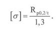
For shells, pipes, heads and other elements made of austenitic steel (except flanges) whose deformation (displacement) under operating conditions does not need to be limited, the allowable stresses may be determined in accordance with clause 21 of these Requirements using the minimum value of the proof strength at 0,2 percent permanent deformation and the design wall temperature with a safety factor nт = 1,1, where this is provided for by the standards under which the calculation and design are performed. This value shall not exceed the minimum value of the proof strength at 0,2 percent permanent deformation and a temperature of 20 °C with a safety factor nт = 1,5:
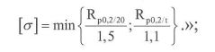
Footnote. Clause 22 as worded by Decision of the Council of the Eurasian Economic Commission No. 49 of 23.04.2021 (enters into force upon expiry of 180 calendar days from the date of its official publication).
23. For steel castings, the allowable stress value determined by the formulas given in clauses 21 and 22 of these Requirements shall be multiplied by 0,8 if the castings have undergone 100% non-destructive testing, or by 0,7 if the castings have not undergone 100% non-destructive testing.
24. Where no data on the yield strength and creep rupture strength are available for aluminium, copper and their alloys, the allowable stress shall be determined by the following formula:

25. In the development (design) and manufacture (production) of equipment made of non-metallic materials, the ultimate tensile strength and tensile modulus of elasticity values for non-metallic materials shall correspond to the values set out in the design documentation and shall be as follows:
a) for a composite based on carbon roving:
ultimate tensile strength [ σ] – not less than 160 kgf/mm2;
modulus of elasticity E – not less than 11 000 kgf/mm2;
b) for composite based on organic-fibre roving:
ultimate tensile strength [ σ] – not less than 170 kgf/mm2;
modulus of elasticity E – not less than 6 500 kgf/mm2;
c) for composite based on glass-fibre roving:
ultimate tensile strength [ σ] – not less than 90 kgf/mm2;
modulus of elasticity E – not less than 5 000 kgf/mm2.
26. Thermoplastic or thermosetting polymer materials may be used as the binder in the equipment.
The curing (polymerisation) temperature of the binder shall be lower than the softening temperature of the non-metallic binder material.
The softening temperature of the material shall be not lower than 100 0C.
27. Welded joints shall have no external or internal defects (damage) that may affect the safety of the equipment. The minimum values of the mechanical properties of the welded joints of the equipment shall be not lower than the minimum values of the mechanical properties of the materials being joined.
28. The manufacturer shall ensure inspection of the welded joints of the equipment. The methods and scope of non-destructive testing are determined by the designer of the equipment (design). They are based on the need for more accurate and complete detection of unacceptable defects, taking into account the properties of the materials, and are specified in the design documentation of the equipment.
Footnote. Paragraph 28 as amended by Decision of the Council of the Eurasian Economic Commission No. 49 of 23.04.2021 (enters into force upon expiry of 180 calendar days from the date of its official publication).
29. In the strength calculation of welded joints of equipment elements, the allowable stress value is multiplied by the weld joint efficiency factor φ< 1. The value of the weld joint efficiency factor is determined in the strength calculation of the equipment depending on the material, the scope of inspection, the welding technology and the weld design.
30. Repealed by Decision of the Council of the Eurasian Economic Commission No. 49 of 23.04.2021 (enters into force upon expiry of 180 calendar days from the date of its official publication).
31. Experimental strength tests of the equipment are carried out on a sample. During the tests, it shall be possible to observe the critical zones of the equipment by means of instrumentation capable of reliably recording strains and stresses.
32. The experimental test programme includes:
a) pressure tests for strength and tightness;
b) creep and fatigue tests of materials, carried out taking into account the operating processes of the equipment;
c) additional tests that take into account the effects of other factors and are carried out where necessary.
Footnote. Paragraph 32 as amended by Decision of the Council of the Eurasian Economic Commission No. 49 of 23.04.2021 (enters into force upon expiry of 180 calendar days from the date of its official publication).33. During the development (design) of the equipment, technical operating characteristics are established that minimise the possibility of an incident or accident during its operation.
34. The equipment is manufactured (produced) from materials and semi-finished products that are specified in the design documentation and that ensure its compliance with the safety requirements throughout its entire service life.
35. The equipment is manufactured (produced) from materials and semi-finished products that bear the marking provided for by the supply contract (without damage). This marking shall allow identification against the documentation data of the manufacturer of the materials or semi-finished products.
36. The manufacturer's marking shall be preserved on sheets, plates, pipes and forgings used in the manufacture (production) of the equipment. If semi-finished products are cut into parts, identical marking shall be applied to each part by the method that was used by the manufacturer of the materials to apply the marking.
37. When selecting materials for the manufacture of equipment (assembly units, parts), the following shall be taken into account: the design pressure, the wall temperature (design and minimum allowable), the chemical composition and nature of the medium, and the processing properties and corrosion resistance of the materials.
Data on the materials used in the manufacture (production) of the equipment are given in the technical documentation.
Footnote. Paragraph 37 as amended by Decision of the Council of the Eurasian Economic Commission No. 49 of 23.04.2021 (enters into force upon expiry of 180 calendar days from the date of its official publication).38. In the manufacture (production) of equipment, materials are used that are:
a) possessing properties (ductility, strength) that allow their use during operation and testing of the equipment. If, when selecting the material, the risk of brittle fracture cannot be reliably excluded due to the design features and operating conditions of the equipment, one or more of the following measures shall be provided to exclude this risk: calculation of the structure for resistance to brittle fracture; increase of the safety factor; stricter inspection requirements at the equipment manufacturing stage; operating regime measures (raising the temperature by the time the pressure reaches the design value, limiting the start-up rate);
b) chemically resistant to the working medium for which the equipment is intended. Changes in the chemical and physical properties of the materials during the entire assigned service life or assigned operating life of the equipment shall not impair its safe operation;
c) suitable for the intended types of processing;
d) selected so that, when joined to each other, they ensure the strength of the equipment throughout the service life of the equipment.
Footnote. Paragraph 38 as amended by Decision of the Council of the Eurasian Economic Commission No. 49 of 23.04.2021 (enters into force upon expiry of 180 calendar days from the date of its official publication).39. A material used in equipment is considered ductile if, in a tensile test, its elongation after fracture is not less than 14 percent and its impact toughness, determined on KCV-type notched specimens (with a V-notch), is not less than 27 J/cm2 at a temperature above 20 0C, but not higher than the minimum allowable temperature.
40. Heat treatment shall be carried out to relieve residual stresses that arise in equipment elements during their manufacture and are unacceptable for the safe operation of the equipment. The need for heat treatment, its type and its modes are determined by the equipment designer.
Footnote. Paragraph 40 as amended by Decision of the Council of the Eurasian Economic Commission No. 49 of 23.04.2021 (enters into force upon expiry of 180 calendar days from the date of its official publication).41. In the manufacture (production) of equipment and safety devices, the manufacturer shall ensure their compliance with the characteristics and parameters specified in the design documentation, in accordance with the safety requirements of the Technical Regulation of the Customs Union "On Safety of Equipment Operating under Excess Pressure" (TR CU 032/2013), taking into account the manufacturing processes and the inspection system applied.
42. In the manufacture (production) of parts by rolling, stamping or edge rounding, changes in the mechanical properties of materials, damage, cracks and other defects that may affect the safety of the equipment are not permitted.
43. Welded and other permanent joints of equipment elements made during manufacture, including at the place of operation, shall be subjected to non-destructive testing, and reporting documents shall be drawn up based on its results. Compliance with this requirement shall be ensured when developing the equipment manufacturing technology.
Welded and other permanent joints of equipment elements shall be accessible for the non-destructive testing provided for by the design documentation and the operating manual (instructions) throughout the entire period of operation of the equipment.
The methods (types) of non-destructive testing are established by the equipment developer.
Footnote. Clause 43 as worded by Decision of the Council of the Eurasian Economic Commission No. 49 of 23.04.2021 (enters into force upon expiry of 180 calendar days from the date of its official publication).44. Equipment fitted with quick-release covers shall have devices that prevent the equipment from being pressurised when the cover is not fully closed and prevent the cover from being opened when excess pressure is present in the equipment.
45. Safety devices and instruments are installed on the boiler to ensure automatic shutdown of the boiler or its elements in the event of unacceptable deviations from the design operating modes.
46. An equipment element whose internal volume is bounded by shut-off valves and in which the pressure may rise above the allowable value is equipped with safety devices that automatically prevent the pressure from rising above the allowable value by discharging the working medium into the atmosphere or into a recovery system.
47. The following are used as safety devices:
a) direct-acting lever-and-weight safety valves;
b) direct-acting spring-loaded safety valves;
c) pilot-operated safety devices consisting of a pilot valve and a main safety valve;
d) safety devices with bursting discs (bursting disc safety devices).
48. Safety devices are located in places accessible for their maintenance.
49. Discharge piping of safety devices and impulse lines of pilot-operated safety devices are equipped with drain piping at points where condensate may accumulate, in order to remove the condensate.
The installation of shut-off valves or other valves on drain piping is not permitted. The medium discharged from safety devices and drains is routed to a safe location. Discharged explosive and flammable, process and toxic Group 1 fluids are directed into closed systems for subsequent recovery, or into controlled combustion systems, or into the atmosphere – for gases with a density relative to air of 0,8 or less.
It is prohibited to combine discharges containing substances that, when mixed, can form explosive mixtures or unstable compounds.
50. The design of the connecting piping of safety devices (inlet, discharge and drain piping) shall exclude the possibility of the working medium freezing in it.
When several safety devices are installed on one nozzle or pipe, the cross-sectional area of the nozzle or pipe shall be at least 1,25 times the total cross-sectional area of the safety valves installed on it. When determining the cross-section of connecting piping longer than 1000 mm, the value of its linear resistance (pressure loss) is taken into account.
51. A lever-and-weight safety valve or a spring-loaded safety valve is equipped with a device for checking the proper functioning of the valve during equipment operation by forced opening. Where forced opening is not permissible due to the properties of the working medium or the conditions of the process, the manufacturer shall determine the procedure and methods for checking the safety valves.
A pilot-operated safety valve is equipped with a device that allows the safety valve to be forcibly opened remotely from the control panel.
The design of spring-loaded safety valves shall exclude the possibility of tightening the spring beyond the value set by adjustment for actuation at the specified pressure. The springs of safety valves are protected against unacceptable heating or cooling, as well as against direct exposure to the working medium.
Footnote. Clause 51 as amended by Decision of the Council of the Eurasian Economic Commission No. 49 of 23.04.2021 (enters into force upon expiry of 180 calendar days from the date of its official publication).52. Equipment whose design pressure is lower than the pressure of its supply source is equipped, on the inlet connecting piping, with an automatic pressure-reducing device with a pressure gauge and a safety valve installed on the lower-pressure side downstream of the pressure-reducing device.
Pressure-reducing and desuperheating stations provide automatic temperature control. If a bypass line is installed, it is also equipped with a pressure-reducing device.
Footnote. Clause 52 as amended by Decision of the Council of the Eurasian Economic Commission No. 49 of 23.04.2021 (enters into force upon expiry of 180 calendar days from the date of its official publication).53. For a group of vessels operating at the same pressure, it is permitted to install 1 pressure-reducing device with a pressure gauge and a safety valve on the common inlet connecting piping upstream of the first branch to one of the vessels. In this case, the installation of safety devices on the vessels themselves is not mandatory if the possibility of a pressure increase in them is excluded.
If an automatic pressure-reducing device cannot operate reliably due to the physical properties of the working medium, the installation of a flow regulator is permitted, provided that protection against pressure increase is provided.
54. The number of safety valves, their dimensions and discharge capacity are determined so that no excess pressure exceeding the design pressure is created in the vessel:
a) by more than 0,05 MPa – for vessels in which the excess pressure is less than 0,3 MPa;
b) by 15 percent – for vessels in which the excess pressure is from 0,3 to 6 MPa inclusive;
c) by 10 percent – for vessels in which the excess pressure is more than 6 MPa.
Footnote. Clause 54 as amended by Decision of the Council of the Eurasian Economic Commission No. 49 of 23.04.2021 (enters into force upon expiry of 180 calendar days from the date of its official publication).55. While the safety valves are operating, the pressure in the vessel may exceed the design pressure by no more than 25 percent, provided that this excess is confirmed by a Strength Calculation and is provided for in the operating manual (instructions) of the vessel.
Footnote. Clause 55 as worded by Decision of the Council of the Eurasian Economic Commission No. 49 of 23.04.2021 (enters into force upon expiry of 180 calendar days from the date of its official publication).56. Safety valves shall protect boilers, superheaters, economizers and piping against a pressure increase of more than 10 percent above the design pressure. A pressure increase of more than 10 percent above the design pressure when the safety valves are fully open is permitted if this is provided for by the Strength Calculation of the boiler, superheater, economizer and piping.
Footnote. Clause 56 as amended by Decision of the Council of the Eurasian Economic Commission No. 49 of 23.04.2021 (enters into force upon expiry of 180 calendar days from the date of its official publication).57. On steam boilers with an operating pressure of more than 4 MPa (except mobile boilers and boilers with a steam output of less than 35 t/h), only pilot-operated safety valves are installed. The installation of lever-and-weight safety valves on the equipment of mobile boiler plants is not permitted.
Footnote. Clause 57 as amended by Decision of the Council of the Eurasian Economic Commission No. 49 of 23.04.2021 (enters into force upon expiry of 180 calendar days from the date of its official publication).58. Safety valves are installed on each steam boiler and hot-water boiler and on each superheater that can be isolated on the working medium side. Their number and installation locations are determined during development (design).
The total discharge capacity of the safety devices installed on boilers shall be not less than the rated capacity of this equipment.
59. The discharge capacity of a safety valve is confirmed by the relevant tests of the prototype of a safety valve of the given design, carried out by its manufacturer, and is stated in the passport of the safety valve.
Footnote. Clause 59 as worded by Decision of the Council of the Eurasian Economic Commission No. 49 of 23.04.2021 (enters into force upon expiry of 180 calendar days from the date of its official publication).60. Safety devices on steam boilers and hot-water boilers are installed on nozzles or pipes directly connected to the boilers, as follows:
a) on natural-circulation steam boilers without a superheater – on the upper drum or steam dome;
b) on once-through steam boilers, as well as on forced-circulation boilers – on the outlet headers or the outlet steam line;
c) on hot-water boilers – on the outlet headers or the drum;
d) on reheaters, all safety devices of the superheater may be installed on the steam inlet side;
e) on economizers that can be isolated on the water side – at least 1 safety device each at the water outlet and inlet.
61. If a boiler has a non-isolable superheater, some of the safety valves, with a discharge capacity of at least 50 percent of the rated capacity of the boiler, are installed on the outlet header of the superheater.
62. On steam boilers with an operating pressure of more than 4 MPa, indirect-acting pilot-operated safety valves are installed on the outlet header of the non-isolable superheater or on the steam line upstream of the main shut-off valves; in drum boilers, for 50 percent of the valves in terms of total discharge capacity, steam for the impulses is taken from the boiler drum.
With an odd number of identical valves, steam for the impulses may be taken from the drum for not less than one third but not more than one half of the valves installed on the steam boiler. In unit-type installations where the safety valves are located on the steam line directly at the turbines, superheated steam may be used for the impulses of all safety valves; in this case, an additional electrical impulse from a contact pressure gauge connected to the boiler drum is supplied to 50 percent of the valves.
With an odd number of identical safety valves, an additional electrical impulse from a contact pressure gauge connected to the boiler drum may be supplied to not less than one third but not more than one half of the valves.
63. For isolable boiler economizers, the installation locations of the safety valves, the method of their adjustment and their opening pressure values are determined by the designer.
On once-through steam boilers in which, during start-up or shutdown of the boiler, the first part of the heating surface (in the direction of water flow) is isolated from the remaining part of the heating surface by shut-off valves, the need for installation, the number and the sizes of safety valves for the first part of the heating surface are determined by the design documentation.
Footnote. Clause 63 as amended by Decision of the Council of the Eurasian Economic Commission No. 49 of 23.04.2021 (enters into force upon expiry of 180 calendar days from the date of its official publication).64. Bursting disc safety devices are installed
on vessels and piping:
a) if lever-and-weight and spring-loaded safety valves cannot be used due to their inertia or for other reasons;
b) upstream of safety valves if the safety valves cannot operate reliably due to the harmful effect of the working medium (corrosion, erosion, polymerisation, crystallisation, sticking, freezing) or due to possible leakage of explosive and fire-hazardous, toxic or environmentally harmful substances through a closed valve. In this case, the equipment must be provided with a device that allows monitoring of the integrity of the bursting disc;
c) in parallel with safety valves to increase the discharge capacity of pressure relief systems;
d) on the outlet side of safety valves to prevent the harmful effect of working media from the discharge system side and to eliminate the influence of back-pressure fluctuations from this system on the reliability of safety valve actuation.
65. The need for and the location of bursting disc safety devices, as well as their design, are determined by the design documentation of the equipment. Bursting discs are installed only in the mounting assemblies intended for them.
Bursting disc safety devices are located in places that are open and accessible for inspection, installation and removal. Connecting piping is protected against freezing of the working medium in it, and the safety devices themselves are installed on branch pipes or piping directly connected to the equipment.
When a bursting disc safety device is installed in series with a safety valve (upstream or downstream of the valve), the cavity between the bursting disc and the safety valve is connected by a branch tube to a signalling pressure gauge (to monitor the integrity of the bursting discs).
Installation of a change-over device upstream of bursting disc safety devices is permitted if a double number of bursting disc devices is provided, while ensuring protection of the equipment against overpressure in any position of the change-over device.
66. To monitor the liquid level in equipment that has a phase interface, liquid working medium level indicators are used. In addition to liquid level indicators, audible, visual and other alarms and interlocks for limit liquid levels are installed on the equipment.
Footnote. Clause 66 as amended by Decision of the Council of the Eurasian Economic Commission No. 49 of 23.04.2021 (enters into force upon expiry of 180 calendar days from the date of its official publication).67. On a steam boiler, except for a once-through boiler, and on a vessel heated by flame or flammable gases in which the liquid level may drop below the permissible level, at least 2 direct-acting liquid level indicators are installed.
It is permitted to additionally install indirect-acting liquid level indicators as backup indicators. The number and locations of liquid level indicators in steam boilers (including those with staged evaporation in drums or with a remote separator), except for once-through boilers, and in vessels heated by flame or flammable gases are determined by the design documentation of the equipment.
68. A direct-acting liquid level indicator must have an independent connection to the equipment. It is permitted to install 2 direct-acting liquid level indicators on a connecting pipe (column) with a diameter of at least 70 mm.
Installation of intermediate flanges and shut-off valves on pipes connecting a direct-acting liquid level indicator to the equipment is not permitted, except for sensors of limit liquid level alarms. This requirement does not apply to flanges of shut-off valves that form part of the liquid level indicator.
Connection of other instruments to a direct-acting liquid level indicator and to its connecting pipes or nozzles is not permitted, except for a sensor of a limit liquid level alarm, provided that this does not impair the operation of the liquid level indicator.
Footnote. Clause 68 as amended by Decision of the Council of the Eurasian Economic Commission No. 49 of 23.04.2021 (enters into force upon expiry of 180 calendar days from the date of its official publication).69. The configuration of pipes connecting liquid level indicators to the equipment must prevent the formation of water pockets in them and ensure that the pipes can be cleaned. Connecting pipes must be protected against heating by fuel combustion products and against freezing.
70. Direct-acting liquid level indicators are located and illuminated so that the liquid level is visible from the workstation of the operating personnel. On equipment with an operating pressure of more than 4 MPa, direct-acting liquid level indicators are provided with casings to protect personnel in the event of failure of the transparent plates.
71. The width of the viewing slot of a liquid level indicator is determined by the design documentation of the equipment.
72. Liquid level indicators are provided with shut-off valves for isolating them from the equipment and for blowdown. The opening and closing directions are indicated on the shut-off valves (cast, stamped or painted), and on a cock the position of its flow passage is additionally indicated. The internal bore diameter of the shut-off valves must be at least 8 mm. For draining water during blowdown of liquid level indicators, funnels with a protective device and a drain pipe are provided to ensure drainage of the equipment.
73. At a pressure in the equipment of more than 4,5 MPa, liquid level indicators are provided with 2 sets of shut-off valves arranged in series for isolating them from the equipment.
74. If the distance from the platform from which the liquid level in the equipment is observed to the direct-acting liquid level indicator is more than 6 m, and also if the liquid level is not visible from the workstation of the operating personnel, 2 lowered remote liquid level indicators are installed. In this case, installation of 1 direct-acting liquid level indicator on the equipment is permitted.
Lowered remote liquid level indicators are connected directly to the equipment by separate nozzles, independently of other liquid level indicators, and have damping devices.
75. On waste-heat boilers and energy-technological boilers, remote liquid level indicators are installed on the control panel (panels) of these boilers.
76. Electrically heated steam boilers are equipped with a system for automatic disconnection of the power supply when the liquid level drops below the limit permissible level.
77. Boilers are equipped with automatic audible and visual alarms for the upper and lower limit water levels. Similar alarms must operate for all parameters at which automatic safety devices and instruments are actuated to shut down the boiler.
78. Steam boilers, irrespective of type and steam output, are equipped with automatic feedwater supply regulators. Steam boilers with a steam temperature at the outlet of the main superheater or reheater of more than 400 0С are provided with automatic devices for steam temperature control.
79. On boilers with a superheater, measuring instruments for superheated steam temperature are provided on each steam line upstream of the main shut-off valves. On boilers with steam reheating, temperature measuring instruments are installed at the steam inlet and outlet.
80. On natural-circulation boilers with steam superheating with a steam output of more than 20 t/h and on once-through boilers with a steam output of more than 1 t/h, in addition to indicating measuring instruments, measuring instruments with continuous recording of the superheated steam temperature are provided.
81. On superheaters with several parallel sections, in addition to the steam temperature measuring instruments installed on the common superheated steam lines, instruments for periodic measurement of the steam temperature at the outlet of each section are installed, and on steam boilers with a steam temperature of more than 500 0С, such instruments are installed on the outlet part of the superheater coils, 1 measuring instrument per metre of flue gas duct width.
82. On steam boilers with a steam output of more than 400 t/h, measuring instruments with continuous recording of the steam temperature are installed on the outlet part of the superheater coils. On steam boilers with desuperheaters for controlling the steam superheat temperature, measuring instruments for the corresponding values are installed upstream and downstream of the desuperheater.
83. At the water inlet to the economizer and at the water outlet from the economizer, and also on the feedwater piping of steam boilers without economizers, measuring instruments for feedwater temperature are provided.
84. On hot-water boilers, water temperature measuring instruments are installed at the water inlet to the boiler and at the water outlet from the boiler.
85. On hot-water boilers with a heat output of more than 1,163 MW, recording water temperature measuring instruments are installed at the boiler outlet.
Footnote. Clause 85 as worded by Decision of the Council of the Eurasian Economic Commission No. 49 of 23.04.2021 (enters into force upon expiry of 180 calendar days from the date of its official publication).86. To monitor the metal temperature and to prevent it from rising above the allowable values during start-ups, shutdowns and load-change modes of the boiler, measuring instruments for the wall temperature of its elements are provided. The need for installation of temperature measuring instruments, their number and their placement are determined by the designer of the boiler.
87. Vessels operating at varying wall temperatures are equipped with temperature measuring instruments to monitor the rate and uniformity of heating of the vessel body along its length and height, as well as with thermal displacement indicators. The need to equip vessels with temperature measuring instruments and thermal displacement indicators, as well as the allowable heating and cooling rates of vessels, are determined by the designer of the vessel and are specified by the manufacturer in the equipment passport or in the operating manual (instructions).
88. Equipment and its individual cavities with different pressure values are provided with direct-acting pressure measuring instruments.
89. Steam boilers with a steam output of more than 10 t/h and hot-water boilers with a heat output of more than 5,83 MW must be equipped with a recording pressure measuring instrument.
Footnote. Clause 89 as amended by Decision of the Council of the Eurasian Economic Commission No. 49 of 23.04.2021 (enters into force upon expiry of 180 calendar days from the date of its official publication).90. Pressure measuring instruments are located:
a) on the boiler drum;
b) on a boiler with a superheater — on the boiler drum and downstream of the superheater, upstream of the main shut-off valves;
c) on the vessel nozzle or on the piping between the vessel and the shut-off valves;
d) on a once-through boiler — downstream of the superheater, upstream of the main shut-off device.
Footnote. Clause 90 as amended by Decision of the Council of the Eurasian Economic Commission No. 49 of 23.04.2021 (enters into force upon expiry of 180 calendar days from the date of its official publication).91. On hot-water boilers, pressure measuring instruments are installed at the water inlet to the boiler and at the water outlet from the boiler upstream of the shut-off valves.
92. The accuracy class of a pressure measuring instrument must be not lower than:
а) 2,5 – at an operating pressure of not more than 2,5 MPa;
б) 1,5 – at an operating pressure from 2,5 to 14 MPa inclusive;
в) 1 – at an operating pressure of more than 14 MPa.
93. Where a pressure measuring instrument is installed at a height of more than 5 m, a duplicate pressure measuring instrument is provided.
94. The equipment design provides for the possibility of safe blowdown, checking and isolation of the pressure measuring instrument.
95. The type of valves, their number and installation locations are determined by the designer of the equipment on the basis of ensuring safety and the shutdowns of the equipment and its elements provided for in the design documentation.
96. In the case of group feedwater supply to boilers, the pump head is selected taking into account the requirements of the Technical Regulation of the Customs Union "On Safety of Equipment Operating under Excess Pressure" (TR CU 032/2013), and on the basis of the condition of ensuring the feed of the boiler with the highest operating pressure or with the greatest head loss in the feedwater piping.
97. The water supply by feedwater supply devices is determined by the rated steam output of the boilers, taking into account the water consumption for continuous or intermittent blowdown, desuperheating and the operation of pressure-reducing and desuperheating stations and desuperheaters, and taking into account the possibility of water or steam losses.
98. The type, characteristics, number and connection diagram of the feedwater supply devices ensure the safe operation of the boiler during operation, including emergency shutdowns.
99. During the development (design) of piping, it is necessary to:
a) for piping with a nominal diameter of more than 150 mm and a working medium temperature of 300 0C and above, determine in the design documentation the required number of displacement indicators to monitor the thermal expansion of the piping and to observe the correct operation of the support and hanger system;
b) provide devices for the removal of condensate in cases where condensate can form inside pipes that transport vapour-gas working media. These devices must be located at the low points of the piping;
c) take into account the possibility of damage from disturbances of the hydraulic regime and from erosion-corrosion wear;
d) provide measures and means to reduce vibration and to exclude the possibility of catastrophic failure and loss of tightness of piping that is subject to vibration during operation;
e) provide devices that isolate piping branches in cases where this piping contains Group 1 fluids;
f) minimise the hazard of an accidental release of the working medium. Fluid sampling/tapping points must be clearly marked with the name of the working medium;
g) develop technical documentation for underground piping that contains the information necessary for its safe maintenance, inspection and repair (steel grades, diameter, pipe wall thickness, piping length, location of supports, expansion joints, hangers, valves, air vents and drains, welded joints with the distances between them and from them to wells and consumer service connections, location of indicators for monitoring the condition of the piping and the working medium parameters).
100. The design of the pressure chamber must allow inspection (including of the internal surface), cleaning, flushing, blowing through and repair of the pressure chamber.
101. During the development (design) of pressure chambers, the loads that arise during installation and under the effect of inertial forces are taken into account.
102. The duration of stay of persons in the pressure chamber is determined by the design documentation and is stated in the passport. In the case of a long stay of persons in the pressure chamber, compartments with different functional purposes are provided.
103. The design documentation of the equipment must provide pressure-tight penetrators or high-pressure glands for electrical cables. These must ensure mechanical strength, axial and radial tightness, gas tightness of the penetrator as a whole and of its current-carrying elements, and dielectric strength of insulation over the entire pressure range in the pressure chamber.
104. The design of the pressure chamber must allow the pressure chamber to be opened from inside and from outside. The use of locks for closing doors or covers inside the pressure chamber is not permitted.
105. For visual or television observation of conditions inside the pressure chamber and for lighting of the internal space, the design documentation of the equipment provides viewports fitted with an external cover that protects the viewport glass from mechanical damage.
During the development (design) and manufacture (production) of viewports for pressure chambers, light-transmitting materials are used with a safety factor not lower than the safety factor of the pressure chamber shell and with a light transmittance of not less than 85 percent.
106. The design documentation of the equipment provides air supply and gas supply systems for the following purposes:
a) formation of the gas environment in the pressure chamber;
b) operation of the built-in breathing system;
c) maintaining and changing the pressure in the pressure chamber;
d) maintaining and changing the composition of the gas environment in the pressure chamber with respect to oxygen and inert gases;
e) lock transfer.
107. The air supply and gas supply systems ensure a pressure increase in the pressure chamber at a rate of not less than 0,2 MPa/min for pressures from 0,1 to 1,7 MPa inclusive (1 – 17 kgf/cm2) and not less than 0,1 MPa/min (1 kgf/cm2 • min) for pressures above 1,7 MPa (17 kgf/cm2). They also ensure that the pressure is maintained with an accuracy of ± 0,025 MPa (0,25 kgf/cm2). The pressure in the pressure chamber is reduced at a rate of 0,003 – 0,9 MPa/h (0,03 – 9 kgf/cm2 • h);
108. The gas monitoring equipment of the pressure chamber must ensure accurate measurement of the content of oxygen, helium and carbon dioxide, and of possible harmful substances.
109. The fire protection system and equipment must ensure detection of the onset of a fire in the pressure chamber or of fire precursors (smoke, uncontrolled temperature rise), activation of an alarm signal, and extinguishing of the detected fire with all means available in the pressure chamber.
110. The automatic control equipment must ensure safe conditions for the stay of persons inside the pressure chamber.
111. Each compartment and lock of the pressure chamber is equipped with a pressure gauge. The pressure gauge is installed outside on a nozzle welded to the pressure chamber shell or on the control panel of the pressure chamber systems.
112. The power networks of the pressure chamber must have backup power sources that ensure uninterrupted operation of the elements of the air supply and gas supply systems and of the fire protection systems and equipment.
113. All switching and protective devices and all starting and control gear of the power electrical equipment are installed outside the pressure chambers. Power cables in the pressure chamber must have non-combustible insulation. The design documentation of the pressure chamber must provide a system of protection against static electricity and the possibility of earthing the internal removable metal items, the equipment and the pressure chamber shell.
114. The design documentation of the equipment determines whether lighting must be installed. Luminaires installed inside the pressure chamber must be sealed and rated for the operating pressure of the medium.
115. The design documentation of the equipment provides for the possibility of using means of communication with persons inside the pressure chamber.
116. Piping and steam and water heaters installed inside the pressure chamber, as well as piping for the supply of compressed air and gas mixtures installed outside the pressure chamber, are designed from seamless copper pipes or stainless steel pipes.
117. For the internal equipment of the pressure chamber, non-combustible (fire-retardant) materials are used that are guaranteed not to release harmful substances into the gas environment of the pressure chamber.
ANNEX No. 3
to the Technical Regulation
of the Customs Union "On Safety
of Equipment Operating under
Excess Pressure"
(TR CU 032/2013)
REQUIREMENTS
for distinctive colouring and identification information
Footnote. Annex 3 as amended by Decision of the Council of the Eurasian Economic Commission No. 49 of 23.04.2021 (enters into force upon expiry of 180 calendar days from the date of its official publication).
I. Cylinders
Gas name | Cylinder colour | Lettering text | Lettering colour | Band colour |
1 | 2 | 3 | 4 | 5 |
Nitrogen | black | nitrogen | yellow | brown |
Ammonia | yellow | ammonia | black | - |
Crude argon | black | crude argon | white | white |
Technical-grade argon | black | technical-grade argon | blue | blue |
Pure argon | grey | pure argon | green | green |
Acetylene | white | acetylene | red | _ |
Butylene | red | butylene | yellow | black |
Petroleum gas | grey | petroleum gas | red | _ |
Butane | red | butane | white | _ |
Hydrogen | dark green | hydrogen | red | _ |
Air | black | compressed air | white | _ |
Helium | brown | helium | white | _ |
Nitrous oxide | grey | nitrous oxide | black | _ |
Oxygen | light blue | oxygen | black | _ |
Medical oxygen | light blue | medical oxygen | black | _ |
Hydrogen sulphide | white | hydrogen sulphide | red | red |
Sulphur dioxide | black | sulphur dioxide | white | yellow |
Carbon dioxide | black | carbon dioxide | yellow | - |
Phosgene | khaki | _ | _ | red |
Freon-11 | aluminium | freon-11 | black | blue |
Freon-12 | aluminium | freon-12 | black | _ |
Freon-13 | aluminium | freon-13 | black | 2 red |
Freon-22 | aluminium | freon-22 | black | 2 yellow |
Chlorine | khaki | _ | _ | green |
Cyclopropane | orange | cyclopropane | black | _ |
Ethylene | violet | ethylene | red | _ |
All other flammable gases | red | gas name | white | _ |
All other non-flammable gases | black | gas name | yellow | _ |
Notes: |
1. The lettering shall be applied along the circumference of the cylinder over a length of at least 1/3 of the circumference, and the band shall be applied around the entire circumference. The letter height on cylinders with a volume of more than 12 l shall be 60 mm, and the band width shall be 25 mm. On cylinders with a volume of up to 12 l, the dimensions of the letters and bands shall be determined according to the size of the lateral surface of the cylinders. |
II. Road tankers for the transportation of liquefied
petroleum gases
The external surface of road tankers for the transportation of liquefied petroleum gases (LPG) shall be painted light grey. A distinctive red band at least 200 mm wide shall be applied to both sides of the vessel, with the black lettering "Propane – FLAMMABLE" above it. The black lettering "FLAMMABLE" shall be applied to the rear head of the vessel.
ANNEX No. 3
to the Technical Regulation
of the Customs Union "On Safety
of Equipment Operating under
Excess Pressure"
(TR CU 032/2013)
REQUIREMENTS
for distinctive colouring and identification information
I. Cylinders
Gas name | Cylinder colour | Lettering text | Lettering colour | Band colour |
1 | 2 | 3 | 4 | 5 |
Nitrogen | black | nitrogen | yellow | brown |
Ammonia | yellow | ammonia | black | - |
Crude argon | black | crude argon | white | white |
Technical-grade argon | black | technical-grade argon | blue | blue |
Pure argon | grey | pure argon | green | green |
Acetylene | white | acetylene | red | _ |
Butylene | red | butylene | yellow | black |
Petroleum gas | grey | petroleum gas | red | _ |
Butane | red | butane | white | _ |
Hydrogen | dark green | hydrogen | red | _ |
Air | black | compressed air | white | _ |
Helium | brown | helium | white | _ |
Nitrous oxide | grey | nitrous oxide | black | _ |
Oxygen | light blue | oxygen | black | _ |
Medical oxygen | light blue | medical oxygen | black | _ |
Hydrogen sulphide | white | hydrogen sulphide | red | red |
Sulphur dioxide | black | sulphur dioxide | white | yellow |
Carbon dioxide | black | carbon dioxide | yellow | _ |
Phosgene | khaki | _ | _ | red |
Freon-11 | aluminium | freon-11 | black | blue |
Freon-12 | aluminium | freon-12 | black | _ |
Freon-13 | aluminium | freon-13 | black | 2 red |
Freon-22 | aluminium | freon-22 | black | 2 yellow |
Chlorine | khaki | _ | _ | green |
Cyclopropane | orange | cyclopropane | black | _ |
Ethylene | violet | ethylene | red | _ |
All other flammable gases | red | gas name | white | _ |
All other non-flammable gases | black | gas name | yellow | _ |
Notes: | 1. The lettering shall be applied along the circumference of the cylinder over a length of at least 1/3 of the circumference, and the band shall be applied around the entire circumference. The letter height on cylinders with a volume of more than 12 l shall be 60 mm, and the band width shall be 25 mm. On cylinders with a volume of up to 12 l, the dimensions of the letters and bands shall be determined according to the size of the lateral surface of the cylinders. 2. Small-capacity cylinders (up to 12 l) for breathing apparatus and self-rescuers with compressed air may be painted grey or yellow. |
II. Road tankers for the transportation of liquefied
petroleum gases
The external surface of road tankers for the transportation of liquefied petroleum gases (LPG) shall be painted light grey. A distinctive red band at least 200 mm wide shall be applied to both sides of the vessel, with the black lettering "Propane – FLAMMABLE" above it. The black lettering "FLAMMABLE" shall be applied to the rear head of the vessel.


