

In accordance with Article 13 of the Agreement on Common Principles and Rules of Technical Regulation in the Republic of Belarus, the Republic of Kazakhstan and the Russian Federation of 18 November 2010, the Customs Union Commission (hereinafter, the Commission) has decided:
1. To adopt the Technical Regulation of the Customs Union "On the Safety of Wheeled Vehicles" (TR CU 018/2011) (attached).
2. Ceased to be in force by Decision of the Board of the Eurasian Economic Commission of 25.12.2018 No. 219 (enters into force upon expiry of 30 calendar days from the date of its official publication).3. To establish that:
3.1. The Technical Regulation of the Customs Union "On the Safety of Wheeled Vehicles" (hereinafter, the Technical Regulation) shall enter into force on 1 January 2015.
3.2. Conformity assessment (confirmation) documents attesting conformity with mandatory requirements established by regulatory legal acts of the Customs Union or by the legislation of a Member State of the Customs Union, which were issued or adopted in respect of products that are objects of technical regulation of the Technical Regulation (hereinafter, the products) before the date of entry into force of the Technical Regulation, shall remain valid until the end of their period of validity, but not later than 1 July 2016. This does not apply to batches of vehicles and components whose period of validity is limited by a quantitative quota.
The said documents issued or adopted before the date of official publication of this Decision shall remain valid until the end of their period of validity.
These documents may also be used as supporting evidence for the purpose of verification of compliance with the requirements of this Technical Regulation, including for the extension of the said documents to the territory of all Member States of the Customs Union.
When the documents referred to in the first indent of this paragraph are extended in accordance with the procedure established by this Technical Regulation, the requirements that were in force before the entry into force of this Technical Regulation at the time the said documents were issued shall apply. In such a case, the period of validity of the document issued on the basis of the Technical Regulation shall correspond to the period of validity of the document that was in force before the entry into force of this Technical Regulation.
From the date of entry into force of the Technical Regulation, the issuance or adoption of conformity assessment (confirmation) documents attesting conformity of products with mandatory requirements previously established by regulatory legal acts of the Customs Union or by the legislation of a Member State of the Customs Union shall not be permitted;
3.2.1 Type approvals for vehicles of categories N3, О3 and О4 issued in the Republic of Belarus and the Russian Federation
in accordance with national legislation before the entry
into force of the Technical Regulation shall have direct effect in the territory of the Republic of Kazakhstan until the end of their period of validity, but not later than
1 July 2016;
3.2.2. The number of vehicles placed on the market in the territory of the Republic of Kazakhstan in accordance with subparagraph 3.2.1 of this Decision shall not exceed 2100 units for category N3 and 2100 units for categories О3 and О4
3.2.3. Conformity assessment (confirmation) documents attesting conformity with mandatory requirements established by the legislation of the Republic of Kazakhstan, which were issued or adopted before the date of entry into force of the Technical Regulation in respect of the "Toyota" vehicle (commercial name "Fortuner") manufactured
in the territory of the Republic of Kazakhstan, shall remain valid until 28 March 2017 inclusive;
3.2.4. The number of vehicles placed on the market from 1 July 2016 in the territory of the Republic of Kazakhstan in accordance with subparagraph 3.2.3 of this Decision shall not exceed 1900 units;
3.2.5. until 31 January 2024 inclusive, the following is permitted for vehicles (chassis) of categories M1, M2, M3, N1, N2 and N3 (except vehicles for the carriage of dangerous goods and vehicles specially intended for the carriage of children) that are manufactured in the customs territory of the Eurasian Economic Union and in respect of which Vehicle Type Approvals (Chassis Type Approvals) are in effect: not to equip them with an emergency call device or system, or to retrofit them with a device or system that complies with mandatory requirements established by regulatory legal acts of a Member State of the Eurasian Economic Union adopted in accordance with the second indent of paragraph 1 of the Technical Regulation.
The vehicles (chassis) referred to in the first indent of this subparagraph shall be retrofitted with an emergency call device or system by the manufacturer of the vehicle (chassis) before 31 December 2027.
The vehicles (chassis) referred to in the first indent of this subparagraph that are placed on the market without emergency call devices or systems from the date of entry into force of this Decision until 31 January 2024 may be sold only on the following conditions: consumers shall be informed that the vehicle (chassis) must be retrofitted with an emergency call device or system, and the relevant information shall be entered in the electronic vehicle passport (electronic vehicle chassis passport).
If vehicles (chassis) manufactured in the territory of one Member State of the Eurasian Economic Union and in operation in its territory are not retrofitted with an emergency call device or system that complies with the requirements of the Technical Regulation, the provisions of the second indent of subparagraph 3.2.6 of this Decision shall apply to such vehicles (chassis) from 31 December 2027.
Control over the implementation of this Decision shall be ensured by the competent authorities of the Member States of the Eurasian Economic Union in accordance with the legislation of the Member States.
Footnote. The Decision was supplemented with paragraph 3.2.5 in accordance with Decision of the Board of the Eurasian Economic Commission of 17.08.2021 No. 101 (enters into force upon expiry of 30 calendar days from the date of its official publication); as amended by Decisions of the Board of the Eurasian Economic Commission of 21.12.2021 No. 183 (enters into force upon expiry of 30 calendar days from the date of its official publication); of 14.06.2022 No. 92 (enters into force upon expiry of 30 calendar days from the date of its official publication); of 23.09.2022 No. 161 (enters into force upon expiry of 10 calendar days from the date of its official publication).3.2.6. The placing on the market and operation of the vehicles referred to in the second indent of paragraph 1 of Section I of the Technical Regulation shall be permitted provided that their safety is ensured, and only in the territory of the Member State of the Eurasian Economic Union in which these vehicles were manufactured, except for the case referred to in the second indent of this paragraph. The issuance of conformity assessment documents provided for by the Technical Regulation in respect of such vehicles shall not be permitted.
The exercise of the rights of possession, use and disposal of the vehicles referred to in the second indent of paragraph 1 of Section I of the Technical Regulation shall not be permitted in the territories of the Member States of the Eurasian Economic Union, except for the territory of the Member State in which these vehicles were manufactured, unless otherwise established by the legislation of the other Member States in respect of such vehicles.
Footnote. Paragraph 3 was supplemented with subparagraph 3.2.6. in accordance with Decision of the Council of the Eurasian Economic Commission of 05.04.2022 No. 45 (enters into force upon expiry of 10 calendar days from the date of its official publication).3.2.7. Until 1 February 2024, in the Republic of Armenia and the Republic of Kazakhstan, the conformity assessment and placing on the market of vehicles of categories М and N that are manufactured in the territory of a Member State of the Eurasian Economic Union or imported into the territory of such a Member State of the Eurasian Economic Union by official representatives of foreign manufacturers shall be permitted without application of paragraphs 113 and 114 of Annex No. 2 to the Technical Regulation and paragraphs 16 and 17 of Annex No. 3 to the Technical Regulation.
Until 31 December 2027, in the Republic of Armenia, the Republic of Belarus, the Kyrgyz Republic and the Russian Federation, the specific procedure for the conformity assessment of vehicles placed on the market without application of the requirements for equipping vehicles with emergency call systems (devices) shall be established by regulatory legal acts of the Government of the Republic of Armenia, the Government of the Republic of Belarus, the Cabinet of Ministers of the Kyrgyz Republic or the Government of the Russian Federation, respectively.
Until 31 December 2028, in the Republic of Armenia, the Republic of Belarus, the Kyrgyz Republic and the Russian Federation, it shall be permitted to establish requirements and a specific procedure for conformity assessment, and to place on the market vehicles imported from third countries by legal entities and individual entrepreneurs, provided that not more than 3 years have elapsed since their date of manufacture. This shall be done in accordance with regulatory legal acts of the Government of the Republic of Armenia, the Government of the Republic of Belarus, the Cabinet of Ministers of the Kyrgyz Republic and the Government of the Russian Federation, respectively. Until 31 December 2028, in the Republic of Kazakhstan, it shall be permitted to establish requirements and a specific procedure for conformity assessment, and to place on the market vehicles imported from third countries by representatives of foreign manufacturers, provided that not more than 3 years have elapsed since their date of manufacture. This shall be done in accordance with regulatory legal acts of the Government of the Republic of Kazakhstan. The issuance of conformity assessment documents provided for by the Technical Regulation in respect of such vehicles shall not be permitted.
The exercise of the rights of possession, use and disposal of the vehicles referred to in the first to third indents of this paragraph shall not be permitted in the territories of the Member States of the Eurasian Economic Union, except for the territory of the Member State of the Eurasian Economic Union in which these vehicles were manufactured or into whose territory they were imported by individual entrepreneurs or legal entities, including official representatives of foreign manufacturers, unless otherwise established by the legislation of the relevant Member States of the Eurasian Economic Union in respect of such vehicles.
Footnote. Paragraph 3 was supplemented with subparagraph 3.2.7 in accordance with Decision of the Council of the Eurasian Economic Commission of 15.04.2022 No. 77 (enters into force upon expiry of 10 calendar days from the date of its official publication); as amended by Decisions of the Council of the Eurasian Economic Commission of 23.09.2022 No. 161 (enters into force upon expiry of 60 days from the date of official publication); of 23.05.2025 No. 45 (enters into force upon expiry of 30 calendar days from the date of its official publication); of 26.09.2025 No. 107 (enters into force upon expiry of 30 calendar days from the date of its official publication); of 05.12.2025 No. 120 (enters into force upon expiry of 10 calendar days from the date of its official publication).3.2.8. Until 1 February 2024, in the Republic of Armenia, the Republic of Belarus, the Republic of Kazakhstan and the Kyrgyz Republic, the conformity assessment and placing on the market of individual vehicles of categories M and N imported for their own needs into the territories of these states shall be permitted without application of the provisions of Section 5 of Annex No. 4 to the Technical Regulation.
The exercise of the rights of possession, use and disposal of the vehicles referred to in the first indent of this subparagraph shall not be permitted in the territories of the other Member States of the Eurasian Economic Union, unless otherwise established by the legislation of the relevant Member States of the Eurasian Economic Union in respect of such vehicles.
Footnote. Paragraph 3.2.8. as amended by Decision of the Council of the Eurasian Economic Commission of 15.02.2023 No. 20 (enters into force upon expiry of 10 calendar days from the date of its official publication).3.2.9.The placing on the market and operation of the vehicles referred to in the third indent of paragraph 1 of the Technical Regulation shall be permitted provided that their safety is ensured, and only in the territory of the state into which such vehicles were imported (the territory of the Republic of Armenia or the territory of the Republic of Belarus). The issuance of conformity assessment documents provided for by the Technical Regulation in respect of such vehicles shall not be permitted.
The exercise of the rights of possession, use and disposal of the vehicles referred to in the third indent of paragraph 1 of the Technical Regulation shall not be permitted in the territories of the Member States of the Eurasian Economic Union, except for the territory of the Republic of Armenia or the territory of the Republic of Belarus, respectively, unless otherwise established by the legislation of the other Member States in respect of such vehicles.
Footnote. Paragraph 3 was supplemented with subparagraph 3.2.9 in accordance with Decision of the Council of the Eurasian Economic Commission of 19.08.2022 No. 120 (enters into force upon expiry of 10 calendar days from the date of its official publication).3.2.10.The placing on the market and operation of the vehicles referred to in the fourth indent of paragraph 1 of Section I of the Technical Regulation shall be permitted in a quantity of not more than 175 units, provided that their safety is ensured, and only in the territory of the Republic of Kazakhstan. The issuance of conformity assessment documents provided for by the Technical Regulation in respect of such vehicles shall not be permitted.
The exercise of the rights of possession, use and disposal of the vehicles referred to in the fourth indent of paragraph 1 of Section I of the Technical Regulation shall not be permitted in the territories of the Member States of the Eurasian Economic Union, except for the territory of the Republic of Kazakhstan.
Footnote. Paragraph 3 was supplemented with subparagraph 3.2.10 in accordance with Decision of the Council of the Eurasian Economic Commission of 15.02.2023 No. 51 (enters into force upon expiry of 10 calendar days from the date of its official publication).3.2.11. The placing on the market and operation of the vehicles referred to in the fifth indent of paragraph 1 of Section I of the Technical Regulation shall be permitted provided that their safety is ensured, and only in the territory of the Republic of Kazakhstan. The issuance of conformity assessment documents provided for by the Technical Regulation in respect of such vehicles shall not be permitted.
The exercise of the rights of possession, use and disposal of the vehicles referred to in the fifth indent of paragraph 1 of Section I of the Technical Regulation shall not be permitted in the territories of the Member States of the Eurasian Economic Union, except for the Republic of Kazakhstan.
Footnote. Paragraph 3 was supplemented with subparagraph 3.2.11 in accordance with Decision of the Council of the Eurasian Economic Commission of 21.04.2023 No. 34 (enters into force upon expiry of 10 calendar days from the date of its official publication).3.3. Until 1 July 2016, the manufacture and placing on the market of products in accordance with mandatory requirements previously established by regulatory legal acts of the Customs Union or by the legislation of a Member State of the Customs Union shall be permitted, provided that conformity assessment (confirmation) documents attesting conformity of the products with the said mandatory requirements were issued or adopted before the date of entry into force of the Technical Regulation.
Such products shall be marked with the national conformity mark (mark of circulation on the market) in accordance with the legislation of the Member States of the Customs Union or with Commission Decision No. 386 of 20 September 2010.
Marking of such products with the single mark of product circulation on the market of the Member States of the Customs Union shall not be permitted;
3.4. The circulation on the market of products placed on the market during the period of validity of the conformity assessment (confirmation) documents referred to in subparagraph 3.2 of this Decision shall be permitted during the shelf life (service life) of the products established in accordance with the legislation of the Member State of the Customs Union.
3.5. If the scheduled surveillance provided for by paragraphs 46 and 47 of the Technical Regulation falls due in 2022, the certification body may, upon the applicant's request, decide to postpone such surveillance for a period of up to 12 months, provided that there is confirmation that the production process of the certified products and the technical documentation for the products have not changed.
3.6. Until 31 December 2024:
3.6.1. Paragraph 25 of the Technical Regulation shall apply with due regard to the fact that authorised representatives of a foreign manufacturer may act as applicants for Vehicle Type Approval (Chassis Type Approval), its extension or renewal.
3.6.2. Paragraph 26 of the Technical Regulation shall not apply.
3.7. Information on the Member State of the Eurasian Economic Union in whose territory the exercise of the rights of possession, use and disposal of the vehicles referred to in the fourth indent of subparagraph 3.2.5 and in subparagraphs 3.2.7 and 3.2.8 of this Decision is permitted shall be entered in the electronic passport of such a vehicle.
If such vehicles are retrofitted with an emergency call device or system that complies with the requirements of the Technical Regulation, the information referred to in the first indent of this subparagraph shall be removed from the electronic vehicle passport.
3.8. Until 31 December 2027 in the Republic of Armenia, the Republic of Belarus and the Kyrgyz Republic, and until 31 December 2030 in the Republic of Kazakhstan, the conformity assessment and (or) placing on the market of vehicles of categories M and N that are manufactured in the territory of a Member State of the Eurasian Economic Union or imported into the territory of such a Member State of the Eurasian Economic Union by representatives of foreign manufacturers shall be permitted without application of paragraph 131 of the Technical Regulation, paragraphs 113 and 114 of Annex No. 2 to the Technical Regulation and paragraphs 16 and 17 of Annex No. 3 to the Technical Regulation. A corresponding note shall be made in the "Additional Information" section of the conformity assessment document of the vehicle and in the vehicle registration certificate of such a vehicle (electronic passport).
Vehicle variants that fully comply with the Technical Regulation shall not be combined within one conformity assessment document with vehicle variants whose conformity assessment was carried out taking into account the requirements referred to in the first indent of this subparagraph.
The exercise of the rights of possession, use and (or) disposal of the vehicles referred to in the first indent of this subparagraph shall not be permitted in the territories of the Member States of the Eurasian Economic Union, except for the Member State of the Eurasian Economic Union in whose territory these vehicles were manufactured or into whose territory they were imported, unless otherwise established by the legislation of the Member States of the Eurasian Economic Union. Until 31 December 2027, the said restrictions shall not apply in the territories of the Member States of the Eurasian Economic Union, except for the territory of the Russian Federation.
If the conformity of the vehicles referred to in the first indent of this subparagraph with the requirements of the Technical Regulation is confirmed during the period of validity of the conformity assessment document issued in accordance with the first indent of this subparagraph, such a document may be used without regard to the provisions of the third indent of this subparagraph.
The provisions of this subparagraph do not restrict the temporary presence and (or) use in the territories of the Member States of the Eurasian Economic Union of the following vehicles placed on the market in accordance with the first indent of this subparagraph: vehicles for the carriage of goods and passengers registered in other Member States of the Eurasian Economic Union, and individual vehicles owned by natural persons of other Member States of the Eurasian Economic Union.
Footnote. Paragraph 3 as amended by Decisions of the Council of the Eurasian Economic Commission of 28.05.2015 No. 27 (enters into force upon expiry of 10 calendar days from the date of its official publication); of 07.06.2016 No. 65 (enters into force upon expiry of 30 calendar days from the date of its official publication); of the Council of the Eurasian Economic Commission of 21.06.2022 No. 103 (enters into force upon expiry of 10 calendar days from the date of its official publication); of 21.06.2022 No. 105 (enters into force upon expiry of 10 calendar days from the date of its official publication); of 19.08.2022 No. 132 (enters into force upon expiry of 10 calendar days from the date of its official publication); of 23.09.2022 No. 161 (enters into force upon expiry of 10 calendar days from the date of its official publication); of 26.09.2025 No. 107 (enters into force upon expiry of 30 calendar days from the date of its official publication).4. The Commission Secretariat, together with the Parties, shall prepare a draft Action Plan necessary for the implementation of the Technical Regulation and, within three months from the date of entry into force of this Decision, ensure that it is submitted to the Commission for approval in accordance with the established procedure.
5. The Russian Party shall:
5.1. At least once every three years, prepare proposals for amendments to the Technical Regulation to keep it up to date in connection with the fulfilment by the Parties of their obligations arising from participation in international agreements on the harmonisation of safety requirements for vehicles.
5.2. At least once a year, ensure that the Lists of Standards referred to in paragraph 2 of this Decision are updated on the basis of monitoring and the results of application of the standards contained in the Lists, as well as proposals from the authorities of the Parties.
5.3. Taking into account the proposals of the Parties, develop a draft programme for the development (amendment, revision) of interstate standards and submit it to the Commission for consideration in accordance with the established procedure.
5.4. By 31 December 2012, develop and submit to the Commission for approval the Rules for completing the forms of Vehicle Type Approvals, Chassis Type Approvals, notices of cancellation of a document attesting conformity with the Technical Regulation, Vehicle Design Safety Certificates and Certificates of Conformity of a Modified Vehicle with Safety Requirements, including requirements for the structure of the numbers and the forms of the said documents.
5.5. Within three months from the date of entry into force of this Decision, develop draft amendments to the Technical Regulation for the purpose of establishing requirements for medical transport vehicles and submit them to the Commission Secretariat in accordance with the established procedure.
6. The Parties shall:
6.1. Before the date of entry into force of the Technical Regulation, designate the state control (supervision) authorities responsible for state control (supervision) of compliance with the requirements of the Technical Regulation, and inform the Commission accordingly;
6.2. From the date of entry into force of the Technical Regulation, ensure state control (supervision) of compliance with the requirements of the Technical Regulation.
7. This Decision shall enter into force 15 days after the date of its official publication, unless the Parties declare the suspension of their approval of the Technical Regulation within this period.
Members of the Customs Union Commission:
For the Republic of Belarus | For the Republic of Kazakhstan | For the Russian Federation |
S. Rumas | U. Shukeyev | I. Shuvalov |
APPROVED
by Decision of the Commission
of the Customs Union
of 9 December 2011 No. 877
TECHNICAL REGULATION
OF THE CUSTOMS UNION
TR CU 018/2011
On the Safety of Wheeled Vehicles
Footnote. Throughout the text of:
the Technical Regulation, Annexes No. 1 – 4, 6, 8 – 10 and 12, Annexes No. 1 and 2 to Annex No. 14 and Annexes No. 1 and 2 to Annex No. 15, the words "UNECE Regulations" in the relevant grammatical case have been replaced by the words "UN Regulations" in the relevant grammatical case (except for the third paragraph of the "Preface" section of the Technical Regulation);
the Technical Regulation and Annexes No. 2 and 12, the words "Global Technical Regulations" in the relevant grammatical case have been replaced by the words "UN Global Technical Regulations" in the relevant grammatical case (except for the third paragraph of the "Preface" section of the Technical Regulation) in accordance with Decision of the Council of the Eurasian Economic Commission No. 29 of 16.02.2018 (enters into force upon expiry of 180 calendar days from the date of its official publication).
Contents
Preface
I. General Provisions
II. Definitions
III. Rules for Circulation on the Market or Putting into Service
IV. Safety Requirements
V. Conformity Assessment
1. Verification of compliance with requirements for types of vehicles (chassis) placed on the market
2. Verification of compliance with requirements for individual vehicles prior to their placing on the market
3. Verification of compliance with requirements for vehicles in use
4. Verification of compliance with requirements for vehicles in use in the event of modification of their design
5. Verification of compliance with requirements for types of vehicle components prior to their placing on the market
VI. Marking with the Single Mark of Product Circulation on the Market
VII. Safeguard Clause
VIII. Final Provisions
Annex No. 1. List of Objects of Technical Regulation Covered by the Technical Regulation of the Customs Union "On the Safety of Wheeled Vehicles"
Annex No. 2. List of Requirements Established for Types of Vehicles (Chassis) Placed on the Market
Annex No. 3. Technical Requirements for Individual Elements and Properties of Objects of Technical Regulation for the Conformity Assessment of Vehicle (Chassis) Types
Annex No. 4. Requirements for Individual Vehicles Placed on the Market
Annex No. 5. Dimensional and Weight Limits Applicable to Vehicles
Annex No. 6. Additional Requirements for Specialised and Special-Purpose Vehicles
Annex No. 7. Requirements for Vehicle Identification
Annex No. 8. Requirements for Vehicles in Use
Annex No. 9. Requirements for Certain Modifications Made to the Vehicle Design
Annex No. 10. List of Requirements for Types of Vehicle Components
Annex No. 11. Division of Vehicles into Types and Variants
Annex No. 12. List of Documents Submitted by the Applicant for the Purpose of Conformity Assessment of Vehicle (Chassis) Types, Individual Vehicles and Vehicle Components with the Requirements of the Technical Regulation of the Customs Union "On the Safety of Wheeled Vehicles"
Annex No. 13. List of Main Issues Examined During the Assessment of Production Conditions, and Rules and Procedure for the Audit of Production Conditions
Annex No. 14. Vehicle Type Approval (Form)
Annex No. 15. Chassis Type Approval (Form)
Annex No. 16. Notice of Cancellation of a Document Attesting Conformity with the Technical Regulation of the Customs Union "On the Safety of Wheeled Vehicles" (Form)
Annex No. 17. Vehicle Design Safety Certificate (Form)
Annex No. 18. Certificate of Conformity of a Modified Vehicle with Safety Requirements (Form)
Annex No. 19. Forms and Schemes of Conformity Confirmation with the Requirements of the Technical Regulation on the Safety of Wheeled Vehicles and Recommendations for Their Selection
Preface
Footnote. Section as amended by Decisions of the Council of the Eurasian Economic Commission No. 29 of 16.02.2018 (enters into force upon expiry of 180 calendar days from the date of its official publication); No. 161 of 23.09.2022 (enters into force upon expiry of 60 days from the date of official publication).
This Technical Regulation has been developed on the basis of the Agreement on Common Principles and Rules of Technical Regulation in the Republic of Belarus, the Republic of Kazakhstan and the Russian Federation (hereinafter – the Customs Union Member States) of 18 November 2010.
Technical regulation of wheeled vehicles is carried out in order to ensure a socially acceptable level of their safety. It also enables the Customs Union Member States to fulfil their obligations arising from their participation in international agreements in the field of wheeled vehicle safety.
The requirements of this Technical Regulation are harmonised with the requirements of the United Nations Regulations (UN Regulations) adopted under the "Agreement concerning the Adoption of Uniform Technical Prescriptions for Wheeled Vehicles, Equipment and Parts which can be Fitted and/or be Used on Wheeled Vehicles and the Conditions for Reciprocal Recognition of Approvals Granted on the Basis of these Prescriptions", concluded in Geneva on 20 March 1958 (hereinafter – the 1958 Agreement); the UN Global Technical Regulations adopted under the "Agreement concerning the Establishing of Global Technical Regulations for Wheeled Vehicles, Equipment and Parts which can be Fitted and/or be Used on Wheeled Vehicles", concluded in Geneva on 25 June 1998 (hereinafter – the 1998 Agreement); and the UN Rules adopted under the "Agreement concerning the Adoption of Uniform Conditions for Periodical Technical Inspections of Wheeled Vehicles and the Reciprocal Recognition of such Inspections", concluded in Vienna on 13 November 1997 (hereinafter – the 1997 Agreement).
The Technical Regulation contains: definitions of the terms used; rules for circulation on the market or putting into service of objects of technical regulation; safety requirements; conformity assessment procedures for vehicle (chassis) types, individual vehicles, vehicles in use and types of vehicle components; requirements for marking products with the single mark of product circulation on the market of the Customs Union Member States; a safeguard clause; final provisions on the application of documents attesting conformity obtained before the entry into force of the Technical Regulation.
The Annexes include:
a list of objects of technical regulation;
requirements for types of vehicles (chassis) placed on the market;
requirements for individual vehicles placed on the market;
dimensional and weight limits applicable to vehicles;
marking requirements;
requirements for vehicles in use;
requirements for certain modifications made to the vehicle design;
requirements for types of vehicle components;
division of vehicles into types and variants;
a list of documents submitted by the applicant for the purpose of conformity assessment;
a list of main issues examined during the assessment of production conditions, and rules and procedure for the audit of production conditions;
forms of documents attesting conformity;
forms and schemes of conformity confirmation and recommendations for their selection.
I. General Provisions
1. For the purposes of protecting human life and health and property, protecting the environment and preventing actions that mislead consumers, this Technical Regulation establishes requirements for wheeled vehicles in accordance with paragraph 16, regardless of their place of manufacture, upon their placing on the market and during their operation in the single customs territory of the Customs Union.
Until 31 December 2027, the Republic of Armenia, the Republic of Belarus, the Kyrgyz Republic and the Russian Federation may establish and apply mandatory requirements for certain wheeled vehicles produced in the territories of the Member States of the Eurasian Economic Union. They may also carry out conformity assessment of such vehicles in accordance with the regulatory legal acts of the Government of the Republic of Armenia, the Government of the Republic of Belarus, the Cabinet of Ministers of the Kyrgyz Republic or the Government of the Russian Federation, respectively, or in the manner established by the legislation of the respective Member States of the Eurasian Economic Union.
Until 1 February 2023, for wheeled vehicles of categories M1 and M1G that are being imported (or have been imported) into the territory of the Republic of Armenia or the territory of the Republic of Belarus by official representatives of foreign manufacturers, conformity assessment against the safety requirements established in this Technical Regulation may be carried out in accordance with the regulatory legal acts of the Government of the Republic of Armenia and the Government of the Republic of Belarus. This excludes items 113 and 114 of the table of the list in accordance with Annex No. 2 and items 16 and 17 of the requirements in accordance with Annex No. 3.
Until 15 October 2023, mandatory requirements may be established and applied for certain wheeled vehicles of category M3 placed on the market in the territory of the Republic of Kazakhstan. Conformity assessment of such vehicles may also be carried out in accordance with the regulatory legal acts of the Government of the Republic of Kazakhstan.
In the Republic of Kazakhstan, until 1 August 2023, conformity assessment and placing on the market are permitted for individual vehicles of category M1 imported into the Republic of Kazakhstan from third countries before 1 September 2022 (not more than 12000 units). This is done without applying the provisions of Section 4 of Annex No. 4 to the Technical Regulation, in accordance with the regulatory legal acts of the Government of the Republic of Kazakhstan.
Footnote. Paragraph 1 as amended by Decisions of the Council of the Eurasian Economic Commission of 05.04.2022 No. 45 (enters into force upon expiry of 10 calendar days from the date of its official publication); of 19.08.2022 No. 120 (enters into force upon expiry of 10 calendar days from the date of its official publication); of 17.10.2022 No. 167 (enters into force upon expiry of 10 calendar days from the date of its official publication); of 15.02.2023 No. 51 (enters into force upon expiry of 10 calendar days from the date of its official publication); of 21.04.2023 No. 34 (enters into force upon expiry of 10 calendar days from the date of its official publication).2. The objects of technical regulation covered by this Technical Regulation include:
wheeled vehicles of categories L, M, N and O intended for operation on public roads (hereinafter referred to as vehicles), as well as chassis;
vehicle components that affect the safety of vehicles.
The objects of technical regulation are established in accordance with Annex No. 1.
3. This Technical Regulation does not apply to vehicles:
1) with a maximum design speed of not more than 25 km/h;
2) intended exclusively for participation in sports competitions;
3) of categories L and M1 for which 30 or more years have passed since their date of manufacture, and of categories M2, M3 and N not intended for the commercial carriage of passengers and goods for which 50 or more years have passed since their date of manufacture, with the original engine, body and, where present, frame, preserved or restored to their original condition;
4) imported into the single customs territory of the Customs Union for a period of not more than 6 months and placed under customs procedures that do not provide for the possibility of alienation;
5) imported into the single customs territory of the Customs Union as personal property by natural persons who are participants in national state programmes for assisting the voluntary resettlement of persons residing abroad, or who have been recognised as refugees or forced migrants in the established manner;
6) belonging to diplomatic and consular missions and to international (interstate) organisations enjoying privileges and immunities in accordance with the generally recognised principles and norms of international law, as well as to the staff of these missions (organisations) and members of their families;
7) off-road heavy-haul vehicles;
8) supplied to ensure national security, including under the state defence order to the armed forces, other troops, military formations and bodies, as well as those transferred from the armed forces, other troops, military formations and bodies for use in the elimination of emergencies and the consequences of natural disasters.
Footnote. Paragraph 3 as amended by Decision of the Council of the Eurasian Economic Commission of 16.02.2018 No. 29 (enters into force upon expiry of 180 calendar days from the date of its official publication).4. This Technical Regulation does not apply to components intended solely for equipping the vehicles specified in subparagraphs 1 – 5, 7 and 8 of paragraph 3 of this Technical Regulation.
Footnote. Paragraph 4 as amended by Decision of the Council of the Eurasian Economic Commission of 16.02.2018 No. 29 (enters into force upon expiry of 180 calendar days from the date of its official publication).5. Ceased to be in force by Decision of the Council of the Eurasian Economic Commission of 16.02.2018 No. 29 (enters into force upon expiry of 180 calendar days from the date of its official publication).
II. Definitions
6. For the purposes of this Technical Regulation, the concepts established by the Agreement on Common Principles and Rules of Technical Regulation in the Republic of Belarus, the Republic of Kazakhstan and the Russian Federation of 18 November 2010 are used, and the following terms are applied with the following meanings:
"automatic (emergency) braking" - braking of a trailer performed by the braking system without any control input from the driver in the event of a rupture of the brake lines of the brake transmission;
"vehicle combination" - a vehicle formed by a motor vehicle and a semi-trailer or trailer (trailers) towed by it;
"anti-lock braking system (ABS)" - a braking system of a vehicle that automatically controls, during braking, the degree of slip of the vehicle wheels in their direction of rotation;
"satellite navigation equipment" - a hardware and software device installed on a vehicle to determine its current location, direction and speed of movement using signals from at least two operational global navigation satellite systems, to exchange data with additional on-board equipment, and to exchange information via mobile radiotelephone networks;
"wheelbase" - the distance between the centres of the wheels of the axles at the maximum mass of the vehicle (for a semi-trailer, the distance between the kingpin axis and the first axle from the kingpin);
"base vehicle" – a vehicle placed on the market which, as a whole, or whose main components in the form of a body or chassis, were used to create another vehicle;
"vehicle safety" - a state characterised by a set of parameters of the design and technical condition of the vehicle that ensure that the risk of harm to the life or health of citizens, to the property of individuals and legal entities, to state or municipal property, or to the environment is prevented or minimised;
"wheel lock" - the cessation of wheel rolling while the wheel moves along the ground;
"armour protection" - a set of armour barriers designed to fully or partially neutralise the effect of weapons;
"ballistic resistance" - the resistance of armour protection to the effect of weapons of a specified type;
"rain flap" - a flexible component of the spray-suppression system, installed behind the wheel and designed to deflect water and to reduce the hazard from small objects thrown up by the tyre;
"ventilation" - the provision of air exchange in the cab and in the passenger compartment of the vehicle;
"off-road heavy-haul vehicles" – power-driven vehicles specially designed, by their construction and purpose, for the carriage of oversized and (or) heavy loads mainly off public roads, for which one of the parameters exceeds the permissible limits established by legislation for travel on public roads, and for which the load on at least one axle exceeds 10 t;
"alteration of vehicle design" – the removal of component parts and items of equipment provided for by the design of a specific vehicle, or the installation of component parts and items of equipment not provided for by that design, carried out after the vehicle has been placed on the market and affecting road safety;
"external lighting devices" - devices for illuminating the road and the registration plate, as well as light-signalling devices;
"restoration of conformity" - a set of measures taken at the production site when products that do not conform to the requirements of this Technical Regulation have been released;
"harmful substances" - impurities contained in the air that have an adverse effect on human health: carbon monoxide, nitrogen dioxide, nitrogen oxide, saturated aliphatic hydrocarbons, formaldehyde and particulate matter;
"braking system response time" - the time interval from the start of braking until the moment at which the deceleration of the vehicle reaches a steady value during road tests, or until the moment at which the braking force reaches its maximum value during tests on test benches, or at which a vehicle wheel locks on the rollers of the test bench;
"endurance braking system" - a wear-resistant (non-friction) braking system designed to reduce the energy load on the brakes of the service braking system of the vehicle;
"emissions" – harmful substances released into the atmospheric air that are contained in the exhaust gases of internal combustion engines and in the fuel evaporation of vehicles, namely carbon monoxide (CO), hydrocarbons (HC), nitrogen oxides (NOx) and particulate matter;
"retractable axle" - an axle that can be raised above the ground by means of an axle-lift device under normal operating conditions of the vehicle;
"placing on the market" - authorisation for interested persons to use and dispose of a vehicle (chassis) or a batch of components without restriction in the single customs territory of the Customs Union;
"hybrid vehicle" - a vehicle that has at least two different energy converters (engines) and two different (on-board) energy storage systems for the purpose of propelling the vehicle;
"mudguard" - a rigid or semi-rigid component of the spray-suppression system, designed to deflect water thrown up by the tyres in motion, and made wholly or partly integral with the body or with other parts of the vehicle (cab, lower part of the loading platform, etc.);
"internal combustion engine" – a heat engine in which the chemical energy of the fuel burning in the working chamber is converted into mechanical work;
"positive-ignition engine " - an internal combustion engine in which ignition of the working mixture is initiated by an electric spark;
"defect" – each individual nonconformity of products with the established requirements;
"diesel engine" - an internal combustion engine operating on the compression-ignition principle;
"particulate matter" – any substance collected on a specified filter medium after dilution of the exhaust gases with clean filtered air at a temperature not exceeding 52 OC;
"vehicle (chassis) identification document" - a document issued by the competent authority of a Member State of the Customs Union for each vehicle (chassis) and containing information on the owner (possessor) of the vehicle (chassis), on the environmental class of the vehicle (chassis), and on the document attesting conformity of the vehicle (chassis) with the requirements of this Technical Regulation;
"individual vehicle" - a vehicle:
- manufactured in the Member States of the Customs Union:
in series production, whose design was individually modified before placing on the market; or individually, outside series production, from an assembly kit; or that is an individually built vehicle; or that is placed on the market from among vehicles previously supplied under a state defence order;
- imported into the single customs territory of the Customs Union:
by an individual for personal use (individual vehicles for personal use are understood as certain types of motor vehicles and motorcycles, and of trailers for motor vehicles and motorcycles, that are determined by the Eurasian Economic Commission as vehicles for personal use), including a vehicle purchased by an individual as e-commerce goods; or
by a legal entity or by an individual registered as an individual entrepreneur, where the vehicle has previously participated in road traffic in states that are not members of the Eurasian Economic Union, provided that more than 3 years have passed since the vehicle was manufactured, including a vehicle intended for sale to individuals as e-commerce goods;
"secondary (emergency) braking system" – a braking system designed to reduce the speed of the vehicle in the event of failure of the service braking system;
"defrosted area" - the area of the outer surface of the windscreen or rear window that has a dry surface, or a surface covered with melted or partially melted frost that can be removed from the outer surface by the windscreen wiper (this area does not include the glass surface covered with dry unmelted frost);
"identification" - establishing that the factory markings on the vehicle (chassis) and its components are identical to the data contained in the documentation submitted by the applicant or in the documents attesting conformity, carried out without disassembly of the vehicle (chassis) or its components;
"manufacturer" - a person who manufactures a vehicle (chassis) or its components with the intention of placing them on the market for sale or for own use;
"innovative vehicle" - a vehicle in which new design solutions are applied that qualitatively change its main performance characteristics, and which cannot be assessed in accordance with this Technical Regulation;
"light source" - one or more elements for generating electromagnetic radiation in the optical region of the spectrum, which may be assembled with one or more transparent envelopes and with a base for mechanical fixing and electrical connection. The end element of a light guide is also a light source;
"reference axis" - a line passing through the axis of symmetry of the filament lamp of a lighting device, or a line perpendicular to the plane tangent to the surface of the lighting device at its geometric centre, that defines the orientation of the direction of light emission;
"vehicle category" – a classification characteristic of a vehicle used for the purpose of establishing requirements in this Technical Regulation;
"protection class" - an indicator of ballistic resistance;
"light source category" - a characteristic of the physical principle of light emission: filament lamp (category 0); filament lamp with a bulb filled with halogen-containing gases (category H), gas-discharge lamp (category D), light-emitting diode (category LED);
"commercial carriage" – the carriage of passengers or goods by wheeled vehicles in connection with entrepreneurial activity, in accordance with the legislation of the Member States of the Customs Union;
"complete vehicle" - a vehicle suitable for operation in accordance with its intended purpose;
"vehicle components" - component parts of the vehicle design supplied to vehicle assembly production and (or) as replacement (spare) parts for vehicles in use;
"air conditioning" - the provision of controlled cooling of the air in the occupant compartment of the vehicle to or below the ambient temperature;
"periodic verification tests" - periodic tests carried out to confirm the stability of the characteristics of manufactured vehicles and vehicle components whose types have undergone conformity assessment against the requirements of this Technical Regulation;
"conspicuity marking" – a series of retro-reflective strips intended to be applied so that they indicate the outline of the vehicle from the side and from the rear.
"headlamp levelling device" - a device for adjusting, manually from the driver's position or automatically, the inclination angle of the light beam of the passing-beam and (or) driving-beam headlamp depending on the vehicle load, and (or) the road profile, and (or) visibility conditions;
"small batch of vehicles (chassis)" - a number of vehicles (chassis) of one type, including all variants, established depending on the vehicle (chassis) category. The maximum size of a small batch is 150 units for categories L1 - L7, M1, O1 - O2, 100 units for categories M2, N1 - N3, O3 - O4, and 50 units for category M3;
"make" - a designation used by the product manufacturer and placed on the product or its packaging;
"mass in running order" - the mass of the complete vehicle with the driver and without load, as specified by the manufacturer. The mass includes at least 90% of the fuel;
"intercity service" - carriage of passengers by bus beyond the boundary of a populated area over a distance of more than 50 km;
"model year" - a period of time determined by the manufacturer during which the manufacturer makes no substantial changes to the design of the vehicles produced. This period may differ from the calendar year in its start, end and duration, but may not exceed 730 days;
"variant" – a design version that differs from other versions belonging to the same type;
"incomplete vehicle" - a vehicle that requires completion before it can be operated;
"neutral position of the steering wheel (steered wheels)" - the position of the steering wheel (steered wheels) corresponding to straight-ahead movement of the vehicle in the absence of disturbing influences;
"obscured zones" - invisible zones that restrict forward field of vision and are created by opaque structural elements of the cab and of the interior and exterior equipment;
"nonconformity" - failure to meet a specified requirement;
"visibility" - a property of the vehicle design that characterises the objective possibility and conditions for the driver to perceive the visual information necessary for safe and effective control of the vehicle;
"occupant compartment" - the interior part of the vehicle used to accommodate the driver (crew) and passengers;
"type approval" - a form of conformity assessment of a vehicle (chassis) against the requirements of this Technical Regulation that are established for the vehicle (chassis) type;
"Vehicle Type Approval" - a document attesting the conformity of vehicles of one type being placed on the market with the requirements of this Technical Regulation;
"Chassis Type Approval" - a document attesting the conformity of chassis of one type being placed on the market with the requirements of this Technical Regulation;
"identification signs" - a graphic representation of information about the departmental affiliation and (or) functional purpose of the vehicle (coats of arms, emblems, logos, etc.);
"optical axis of the headlamp testing and adjustment device" - a line passing through the centre of the lens on the screen built into the headlamp testing and adjustment device;
"optical centre (centre of reference)" - a mark on the outer lens indicating the point where its outer surface is intersected by the reference axis of the lighting device;
"control" - a structural element of the vehicle that the driver acts upon to change the functioning of the vehicle or its parts;
"original components" - components supplied to vehicle assembly production;
"reference axis" – the line of intersection of the planes that pass through the optical centre of the lighting device parallel to the median longitudinal plane of the vehicle and to the ground;
"folding seat" - an auxiliary seat intended for occasional use and normally kept in the folded position;
"heating" - controlled raising of the temperature in the occupant compartment and its maintenance at a set level;
"steering ratio" - the ratio of the steering wheel rotation angle to the mean steering angle of the steered wheels;
"seepage" - the appearance of fluid, detectable by touch, on the surface and at the joints of parts of sealed vehicle systems;
"airbag" – a bag made of flexible material that is inflated with gas when the pyrotechnic gas generator is activated;
"manufacturer's representative" - a legal entity registered in accordance with the established procedure in a Member State of the Customs Union, designated by the manufacturer under an agreement with the manufacturer to act on its behalf in conformity assessment and placing of products on the single customs territory of the Customs Union, and to bear liability, jointly and severally with the manufacturer, for nonconformity of products with the requirements of this Technical Regulation;
"flash duration" - the period of time during which the luminous intensity of a flash of a special warning light exceeds 10% of the maximum luminous intensity;
"median longitudinal plane of the vehicle" - the plane perpendicular to the ground plane and passing through the middle of the vehicle track, intended to improve the passive safety of the vehicle by fixing the position of the driver and passengers relative to the body;
"transparent part of the windscreen and side windows" – the part of the glazing of the windscreen and side windows that is free of opaque structural elements and has a light transmittance of at least 70%;
"operability" - the condition in which the vehicle or its components are able to perform their functions in accordance with the operating documentation;
"service braking system" - a braking system intended to reduce the speed of the vehicle and (or) bring it to a stop;
"loadable axle" - an axle whose load can be varied by means of an axle load-transfer device without the axle being lifted off the ground;
"maximum authorised mass" - the maximum mass of the vehicle established by this Technical Regulation or other regulatory legal acts depending on design features;
"outer lens" - the outermost component of the lighting device, which transmits light through the illuminating surface;
"industrial assembly regime" - a method of organising production established with the participation of a manufacturer of complete vehicles or their components, based on an investment agreement approved by the authorised government body in accordance with the established procedure;
"steering gear" – a mechanism that converts the rotation of the steering wheel into translational movement of the steering linkage, causing the steered wheels to turn;
"steering linkage" – a system of rods and levers that connects the steered wheels of the vehicle to the steering gear;
"self-steering axle" - an axle pivoted at its centre so that it can describe an arc in the horizontal plane (for the purposes of this Technical Regulation, an axle fitted with steered wheels is also a self-steering axle);
"self-tracking wheels" - wheels that are not actuated by the steering equipment of the vehicle but can turn due to friction in the contact area between the tyre and the ground;
"self-propelled chassis" - a vehicle chassis of category N fitted with a cab and an engine, which may temporarily take part in road traffic subject to restrictions;
"assembly kit" - a group of component parts supplied by a vehicle manufacturer to another manufacturer for the final assembly of vehicles;
"light source module" - the light-emitting part of a lighting and light-signalling device of a vehicle, consisting of optical, mechanical and electrical elements and intended to form or amplify the light beam from the light source;
"Vehicle Design Safety Certificate" - a document attesting the conformity of an individual vehicle being placed on the market with the requirements of this Technical Regulation;
"air/water separator" - a component forming part of the outer valance and (or) rain flap, which allows air to pass while reducing water spray;
"certification tests" - tests of a representative sample (samples) of a vehicle or vehicle component, on the basis of the results of which a conclusion is made on the conformity with the requirements of this Technical Regulation of the vehicle type or vehicle component type that covers the variants included in the technical description submitted by the applicant for certification tests;
"spray-suppression system" - devices intended to provide protection against the spray of water thrown up by the tyres of a moving vehicle;
"exhaust aftertreatment system" - a set of components that reduce emissions of polluting substances in exhaust gases during engine operation;
"washer system" - a system consisting of a device for storing fluid and delivering it to the outer surface of the glazing, together with controls for activating and stopping the device;
"emergency call system" - a system that performs the functions of an emergency call device and ensures automatic transmission of a message about the vehicle in the event of a road traffic accident or other incident;
"cleaning system" - a system consisting of a device for cleaning the outer surface of the glazing, together with additional fittings and controls for activating and stopping the device;
"vehicle speed" - the linear speed of the vehicle's centre of mass;
"communication concerning UN approval" - a document issued under the 1958 Agreement attesting the conformity of a vehicle or its component with the requirements of UN Regulations;
"articulated vehicle" - a vehicle consisting of two or more rigid sections articulated to each other, which can be separated only by means of special equipment;
"specialised passenger vehicle" - a vehicle of category M2G or M3G built on the chassis of an off-road vehicle of category N1G, N2G or N3G;
"specialised vehicle" - a vehicle intended for the carriage of certain types of goods (petroleum products, food liquids, liquefied petroleum gases (LPG), food products, etc.);
"special-purpose vehicle" - a vehicle intended to perform special functions that require special equipment (truck cranes, fire-fighting vehicles, vehicles fitted with vehicle-mounted aerial work platforms, recovery vehicles, etc.);
"steering self-centring" - a property of the steering equipment whereby the steered wheels and the steering wheel, once displaced from the neutral position, return to that position by themselves after the force is removed from the steering wheel while the vehicle is in motion;
"percentage of cleared area of the test area" - the ratio of the surface area of the test area cleaned by the windscreen wiper blades to the total surface area of the corresponding test area, expressed as a percentage;
"A-pillars" - cab roof supports together with the adjacent opaque elements of doors and seals, or the opaque strip along the edges of bonded glazing (a central A-pillar may not be a cab roof support);
"parking braking system" - a braking system intended to hold the vehicle stationary;
"total steering free play" - the angle of rotation of the steering wheel from the position corresponding to the start of turning of the steered wheels in one direction to the position corresponding to the start of their turning in the opposite direction, measured from the position corresponding to straight-ahead motion of the vehicle;
"Technical Service" - an organisation authorised to conduct tests for UN approval of a vehicle type under the 1958 Agreement;
"technical examination of vehicle design" - analysis of the vehicle design and of its technical documentation without conducting tests;
"technically permissible maximum laden mass" - the maximum mass of the vehicle with equipment, passengers and load, established by the manufacturer and determined by the vehicle design and its specified characteristics;
"technically permissible maximum laden mass of the combination" - the maximum combined mass of the towing vehicle and the semi-trailer or trailer(s) towed by it, with equipment, passengers and load, established by the manufacturer;
"technically permissible maximum mass on the axle (axle group)" - the mass corresponding to the maximum permissible static vertical load transmitted by the axle (axle group) to the ground, determined by the design of the axle (axle group) and of the vehicle, and established by the vehicle manufacturer;
"technically permissible maximum load on the fifth-wheel coupling" - the value corresponding to the maximum permissible static vertical load transmitted by the semi-trailer to the towing vehicle through the fifth-wheel coupling, established by the manufacturer of the towing vehicle for the towing vehicle and by the manufacturer of the semi-trailer for the semi-trailer;
"technically permissible maximum load on the coupling device" - the value corresponding to the maximum permissible static vertical load on the coupling device (excluding the load from the mass of the coupling device of vehicles of categories M and N), determined by the design of the vehicle and/or of the coupling device, and established by the vehicle manufacturer;
"technical inspection" - a check of the technical condition of a vehicle in use;
"vehicle maintenance" - a set of operations prescribed by the manufacturer and performed at specified intervals to keep the vehicle or its components in working order during operation, in order to reduce the risk of failures and malfunctions;
"technical description" - a description of the technical characteristics and main parameters, prepared by the manufacturer (applicant), that identifies the design of the vehicle (component) submitted for assessment of conformity with the requirements of this Technical Regulation;
"technical condition" – the set of vehicle properties that are subject to change during operation and of vehicle parameters established by regulatory documents, which determines whether the vehicle can be used for its intended purpose;
"vehicle type (chassis type, component type)" - vehicles (chassis, components) with common design features recorded in the technical description and manufactured by one manufacturer;
"braking" - the process of generating and varying artificial resistance to the motion of the vehicle;
"braking force" - the reaction of the ground on a vehicle wheel that causes deceleration of the wheel and/or of the vehicle;
"braking system" - the combination of vehicle parts intended for braking the vehicle when the braking system control is actuated;
"brake transmission" - the combination of parts of the braking control intended for the controlled transfer of energy from its source to the brakes in order to effect braking;
"braking distance" - the distance travelled by the vehicle from the beginning to the end of braking;
"vehicle" - a wheeled device of categories L, M, N, O intended for the carriage of persons, goods or equipment mounted on it;
"aiming angle of the beam of passing-beam headlamps or front fog lamps of a vehicle" - the angle between the inclined plane containing the flat upper (left) boundary of the beam of the passing-beam headlamp or front fog lamp and the horizontal plane passing through the optical centre of the headlamp;
"power-to-mass ratio" – the ratio of the maximum net engine power to the technically permissible maximum laden mass of the vehicle, in kW/t;
"steered wheels" - wheels actuated by the steering equipment of the vehicle;
"emission level" – the emission limit values that represent the maximum permissible mass of emissions into the atmosphere per unit of work performed or distance travelled by the vehicle and the internal combustion engine;
"mean fully developed deceleration (MFDD)" - the average deceleration during braking, from the end of the deceleration build-up period to the start of its decline at the end of braking;
"vehicle stability during braking" - the ability of the vehicle to move during braking within the specified traffic corridor;
"spray-suppression device" - a component of the spray-suppression system that may be designed as an energy-absorber type device or as an air/water separator;
"axle load-relief device" - a device intended to reduce or increase the load on the axle(s) depending on the road conditions in which the vehicle is driven, in order to reduce tyre wear when the vehicle is partially laden, and/or to improve the starting conditions of the vehicle (vehicle combination) on slippery roads by increasing the load on the powered axle;
"emergency call device" - a device that determines the coordinates, speed and direction of travel of the vehicle using signals from at least two operational global navigation satellite systems, transmits a message about the vehicle in manual mode in the event of a road traffic accident or other incident, and provides two-way voice communication with emergency services via mobile radiotelephone networks;
"DR, DC, DCR type headlamps" - headlamps with gas-discharge light sources of category D: DR driving-beam headlamps, DC passing-beam headlamps, and DCR dual-mode (passing and driving beam) headlamps;
"HR, HC, HCR type headlamps" - headlamps with halogen light sources of category H: HR driving-beam headlamps, HC passing-beam headlamps, and HCR dual-mode (passing and driving beam) headlamps;
"R, C, CR type headlamps" - headlamps with filament lamp light sources of category 0: R driving-beam headlamps, C passing-beam headlamps, and CR dual-mode (passing and driving beam) headlamps;
"Type B and Type F3 headlamps" - front fog lamps that differ in photometric characteristics and in the marking applied to the lamp;
"windscreen washer nozzle" - a device that directs the washer fluid onto the windscreen;
"cold brake" - a brake whose temperature, measured on the friction surface of the brake drum or brake disc, is below 100 0С;
"colour-and-graphic scheme" - a graphic representation of the layout, configuration and compositional relationship of the base colour, decorative stripes, identification signs and information inscriptions applied to the exterior surface of the vehicle;
"wiper cycle" - one forward and one return stroke of the wiper blade;
"chassis" - a wheeled device that is not equipped with a cab and/or an engine and/or a body, and is not intended for operation as a vehicle;
"anti-skid stud" - a hard profiled pin consisting of a body and a wear-resistant insert, installed in a tread block of a winter tyre to improve the grip of the tyre on icy or snow-covered road surfaces;
"environmental class" - a classification code characterising the design of a vehicle or internal combustion engine according to the emission level and the level of requirements for on-board diagnostic systems;
"operation" - the stage of the vehicle life cycle in which the vehicle is used for its intended purpose, from the moment of its State Registration until its disposal;
"energy-absorber type device" - a component forming part of the mudguard and/or the outer side panel and/or the splash guard, which absorbs the energy of water and reduces spray;
"power unit of a hybrid vehicle" – the combination of an internal combustion engine, an electric motor, a generator (the functions of the motor and the generator may be performed by a single electric machine), an energy storage device, power converters and a control system;
"braking performance" - the property characterising the ability of the braking system to generate the required artificial longitudinal resistance to the motion of the vehicle.
Footnote. Paragraph 6 as amended by Decisions of the Council of the Eurasian Economic Commission No. 6 of 30.01.2013 (enters into force upon expiry of 30 calendar days from the date of its official publication); No. 45 of 23.05.2025 (enters into force upon expiry of 90 calendar days from the date of official publication); No. 121 of 05.12.2025 (enters into force on the date of entry into force of the Protocol on Amendments to the Treaty on the Customs Code of the Eurasian Economic Union of 11.04.2017, signed on 25.12.2023).III. Rules for Circulation on the Market or Putting into Service
7. Vehicles and their components shall be permitted for circulation on the market if they conform to this Technical Regulation. Such conformity is confirmed by their marking with the single mark of product circulation on the market in accordance with Section VI of this Technical Regulation.
The date of placing on the market of a vehicle (chassis) is the date of issue of the vehicle identification document for the vehicle (chassis).
8. The documents attesting conformity with the requirements of this Technical Regulation upon placing on the market are:
for vehicles whose conformity assessment was carried out in the form of type approval – the Vehicle Type Approval;
for chassis – the Chassis Type Approval;
for individual vehicles – the Vehicle Design Safety Certificate;
for vehicle components – the declaration of conformity or the certificate of conformity.
The registration number of each document attesting conformity with the requirements of this Technical Regulation contains a single designation confirming its validity in the single customs territory of the Customs Union. It also contains the distinguishing designation of the State in which the document was issued.
9. Documents issued based on the results of a conformity assessment of products carried out in one of the Member States of the Customs Union in the procedure established by this Technical Regulation are valid in all Member States of the Customs Union.
IV. Safety Requirements
10. The manufacture of vehicles from used components is prohibited, except for vehicles manufactured for personal use.
11. It is prohibited to install on vehicles of categories M1 and N1 structures made of steel or other materials with similar strength characteristics that project forward of the bumper line corresponding to the outer contour of the projection of the vehicle onto the horizontal plane of the ground. This requirement does not apply to structures provided for in the standard equipment of the vehicle and (or) that have undergone conformity assessment in the established procedure. It also does not apply to metal grilles weighing less than 0,5 kg intended to protect the headlamps only, or to the registration plate and its mounting elements.
12. Air conditioners and refrigeration equipment used on vehicles shall not contain ozone-depleting substances and materials included in the list approved by the Customs Union Commission.
13. The following vehicles placed on the market shall be equipped with satellite navigation equipment: vehicles of category M used for the commercial carriage of passengers, as well as those specially intended for the carriage of children; vehicles of category N used for the transport of municipal solid waste and refuse (refuse collection vehicles) and for the carriage of special, dangerous, heavy and (or) oversized cargo; and emergency service vehicles. The design of these vehicles shall allow them to be equipped with such equipment.
Emergency service vehicles and vehicles of category N used for the transport of municipal solid waste and refuse (refuse collection vehicles) shall be equipped with satellite navigation equipment in the procedure established by the legislation of the Member States of the Customs Union.
Vehicles in use shall be equipped with such equipment in the procedure established by the legislation of the Member States of the Customs Union.
Footnote. Paragraph 13 as amended by Decision of the Council of the Eurasian Economic Commission No. 6 of 30.01.2013 (enters into force upon expiry of 30 calendar days from the date of its official publication).131. Vehicles of category M1 placed on the market that fall within the scope of UN Regulations No. 94 and 95, and vehicles of category N1 that fall within the scope of UN Regulation No. 95, shall be equipped with an emergency call system. Other vehicles of categories M1 and N1 placed on the market, as well as vehicles of categories M2, M3, N2 and N3, shall be equipped with an emergency call device.
Footnote. The Technical Regulation was supplemented by paragraph 131 in accordance with Decision of the Council of the Eurasian Economic Commission No. 6 of 30.01.2013 (enters into force upon expiry of 30 calendar days from the date of its official publication).14. The design of vehicles of categories M2 and M3 placed on the market and engaged in the commercial carriage of passengers, and of vehicles of categories N2 and N3 engaged in the commercial carriage of goods, shall allow them to be equipped (standard installation locations, mountings and power supply) with technical means of monitoring drivers' compliance with driving, working and rest periods (tachographs).
Vehicles shall be equipped with such equipment in the procedure established by the regulatory legal acts of the Member States of the Customs Union.
The requirements of this paragraph do not apply to the vehicles specified in Article 2 of the European Agreement concerning the Work of Crews of Vehicles Engaged in International Road Transport (AETR).
15. The interface of vehicles (chassis) placed on the market (the set of elements that enables the user to interact with electronic systems, including the receipt of visual and voice information by the user and the input of control commands by the user) shall operate in Russian. Information and warning inscriptions on such vehicles (chassis) shall also be applied in Russian.
This requirement applies during conformity assessment in the form of type approval to:
messages displayed on information screens (displays) or voice warning messages about malfunctions of vehicle systems, about hazards to human life and health, and about the activation of individual vehicle safety systems;
inscriptions on plates1 and labels1 on the vehicle that inform about the safe use of the vehicle and its systems.
Provided that an appropriate translation and (or) explanation is given in the operating manual of the vehicle, this requirement does not apply to:
messages on information screens (displays) of audio, video, gaming and other multimedia systems;
abbreviations;
inscriptions applied to the controls and structural elements of the vehicle;
units of measurement;
company names, trade names of vehicles, and names of the systems and vehicle components used on them;
UN approval markings provided for by the mandatory requirements of UN Regulations and Global Technical Regulations.
messages and inscriptions specially intended for service station personnel.
16. Safety requirements are implemented through compliance with UN Regulations, Global Technical Regulations and the provisions of this Technical Regulation directly, in accordance with:
1) paragraphs 11-15 and Annexes No. 2 and 3 – for types of vehicles (chassis) placed on the market, during conformity assessment in the form of type approval;
2) paragraphs 11-15 and Annexes No. 4 and 8 – for individual vehicles placed on the market;
3) Annex No. 5 – for dimension and weight limits of vehicles placed on the market;
4) Annex No. 6 – for special-purpose and specialised vehicles placed on the market, taking into account their functional purpose;
5) paragraphs 11-14 and Annex No. 8 - for vehicles in use;
6) Annex No. 9 – for vehicles in use in the event of modification of the vehicle design.
For innovative vehicles, the safety requirements, the conformity assessment procedure and the type of conformity document are established by a Decision of the competent authority for technical regulation of the Member State of the Customs Union in which the conformity assessment is carried out. In the Russian Federation, they are established by a regulatory legal act of the Government of the Russian Federation.
Footnote. Paragraph 16 as amended by Decisions of the Council of the Eurasian Economic Commission No. 29 of 16.02.2018 (enters into force upon expiry of 180 calendar days from the date of its official publication); No. 37 of 13.03.2026 (enters into force upon expiry of 30 calendar days from the date of its official publication).17. Vehicles of categories M and N and internal combustion engines for them are divided into environmental classes in accordance with Annex No. 1.
18. Each vehicle has an individual identification number. Requirements for the identification of vehicles (chassis) placed on the market are established in Annex No. 7 to this Technical Regulation.
The requirements for the content of the identification number do not apply to individual vehicles imported into the single customs territory of the Customs Union. They also do not apply to vehicles placed on the market before the entry into force of the Technical Regulation.
19. The placing on the market of right-hand drive vehicles of categories M2 and M3 is prohibited.
In the Republic of Armenia, the Republic of Belarus and the Republic of Kazakhstan, the placing on the market of right-hand drive vehicles of other categories is prohibited.
Footnote. Paragraph 19 as amended by Decision of the Council of the Eurasian Economic Commission No. 66 of 21.06.2019 (enters into force upon expiry of 180 calendar days from the date of its official publication).20. Components placed on the market as replacement (spare) parts for vehicles in use shall not, when installed on a vehicle, reduce its safety level compared to the level at the time the vehicle was placed on the market.
The list of requirements for vehicle component types is established in Annex No. 10 to this Technical Regulation.
Components placed on the market as replacement (spare) parts for vehicles in use and supplied to the assembly production of these vehicles are deemed to meet the requirement of the first subparagraph of this paragraph if the vehicle conforms to the requirements of this Technical Regulation.
21. The requirements for components that are replacement (spare) parts for vehicles no longer in production remain at the level in force at the time production of such vehicles ended.
22. Where this Technical Regulation is applied to vehicles (chassis) and their components supplied for emergency rescue needs and under the state defence order, the list of requirements for them and the forms of conformity assessment are established by the state customer of the Member State of the Customs Union.
V. Conformity assessment
1. Verification of compliance with requirements for types of
vehicles (chassis) placed on the market
23. Verification of compliance with requirements for types of vehicles (chassis) placed on the market is carried out in the form of type approval. The division of vehicles into types and variants for the purposes of conformity assessment is carried out in accordance with Annex No. 11 to this Technical Regulation.
Verification of compliance with requirements for types of chassis manufactured in the Member States of the Customs Union is carried out in cases where the following is envisaged:
1) placing of a self-propelled chassis on the market and (or) movement of the chassis under its own power on public roads to the place of further completion;
2) subsequent allocation of responsibility for compliance with individual requirements of this Technical Regulation between the chassis manufacturer and the manufacturer of the complete vehicle on the basis of a contract between them. If such allocation of responsibility is not envisaged, responsibility for compliance with the requirements of this Technical Regulation rests with the manufacturer of the complete vehicle.
Verification of compliance with requirements for types of chassis imported into the single customs territory of the Customs Union is carried out regardless of the purposes of their subsequent use.
The specific features of verification of compliance with requirements for types of vehicles (chassis) supplied under the state defence order are established by the state customer of the Member States of the Customs Union.
24. Verification of compliance with requirements for types of vehicles (chassis) is carried out by accredited certification bodies that are included in the Unified Register of Certification Bodies and Testing Laboratories (Centres) of the Customs Union and that have been nominated by a Member State of the Customs Union to carry out type approval (hereinafter – certification bodies).
The necessary tests are carried out by testing laboratories whose competence meets the requirements of standard ISO 17025 and that are included in the Unified Register of Certification Bodies and Testing Laboratories (Centres) of the Customs Union (hereinafter – accredited testing laboratories).
25. If vehicles (chassis) are manufactured in the single customs territory of the Customs Union, the applicant for type approval may be a manufacturer that is registered in accordance with the legislation of a Member State of the Customs Union, is a resident of that State and has been assigned a World Manufacturer Identifier (WMI), or an official representative of the manufacturer acting on its behalf.
A manufacturer that is not a resident of a Member State of the Customs Union shall appoint in each Member State of the Customs Union its representative, who bears responsibility jointly with the manufacturer for ensuring that the type-approved products placed on the market comply with the requirements of the Technical Regulation. The manufacturer's representative is a legal entity registered in accordance with the legislation of a Member State of the Customs Union and resident in that State.
All manufacturer's representatives are specified in the Vehicle Type Approval (Chassis Type Approval).
The applicant for type approval of vehicles (chassis) imported into the single customs territory of the Customs Union may be one of the above-mentioned representatives of the foreign manufacturer who is authorised by the manufacturer to carry out conformity assessment of its products against the requirements of this regulation.
A manufacturer that is not a resident of a Member State of the Customs Union and that produces vehicles of different makes and (or) categories may appoint different manufacturer's representatives for each combination of make and (or) category, who act as applicants in the conformity assessment. However, it is not permitted to appoint different manufacturer's representatives for vehicles of different makes but of the same category that have the same World Manufacturer Identifier.
A manufacturer that produces vehicles of different makes registered to another manufacturer may appoint its representative, who may be the applicant for each make. Such a representative may be a legal entity that is the official representative of the manufacturer owning the make concerned.
26. If the authority of the manufacturer's representative that carried out the conformity assessment work is terminated, the documents attesting conformity with the requirements of this Technical Regulation in which the manufacturer's representative whose authority has been terminated is specified also cease to be valid.
27. Mandatory conditions for issuing a Vehicle Type Approval (Chassis Type Approval) are positive results of the production assessment of the manufacturer carried out by the certification body, confirming:
the existence of organisational and technical measures ensuring the stability of product characteristics or production process parameters;
the existence of plans for periodic checks and tests of the manufactured products to confirm their compliance with the requirements of this Technical Regulation;
the existence of instructions concerning the operation of vehicles, as well as their pre-sale preparation, maintenance and repair;
the existence of measures to restore compliance of manufactured vehicles (chassis) and, where necessary, vehicles (chassis) in use with the requirements of this Technical Regulation if nonconformities are detected during checks or tests of vehicles (chassis).
If products of another manufacturer were used in the manufacture of a vehicle, the obligations of each manufacturer may be allocated between them on the basis of a contract (protocol) on mutual obligations. In the absence of such a contract (protocol), the manufacturer of the final product bears full responsibility for the compliance of the product with the requirements of this Technical Regulation.
28. Type approval is carried out in the following order:
1) submission of an application to the certification body specifying the name and details of the applicant, the vehicle type and information on previously issued Vehicle Type Approvals (hereinafter – application). For a vehicle type, one application is submitted to one certification body. The application is accompanied by the documents according to the list in Annex No. 12 to this Technical Regulation;
2) adoption by the certification body of a decision on the application within 15 days, and conclusion of a contract with the applicant for the performance of work. The decision states: whether the documents can be recognised and are sufficient; whether tests are necessary to obtain missing supporting evidence; whether an audit of production conditions is necessary and its timing;
3) identification of the submitted samples of vehicles (chassis) by an accredited testing laboratory, their certification tests and the preparation of reports, each of which is accompanied by a technical description prepared by the manufacturer and certified by the accredited testing laboratory;
4) production assessment of the manufacturer in accordance with paragraph 27;
5) registration of declarations of conformity by the certification body, issuance of certificates of conformity of the vehicle with individual requirements set out in Annexes No. 2, 3 and 6 to this Technical Regulation, and their delivery to the applicant;
6) preparation by the certification body of a conclusion on the possibility of issuing a Vehicle Type Approval (Chassis Type Approval) on the basis of the completion of subparagraphs 3) – 5) of this paragraph, provided that the vehicle (chassis) complies with the requirements of this Technical Regulation in force at the time of issue of the document attesting conformity;
7) issuance of the Vehicle Type Approval (Chassis Type Approval) by the certification body;
8) approval and registration of the Vehicle Type Approval (Chassis Type Approval) by the authorised government body of the Member State of the Customs Union;
9) surveillance by the certification body of the compliance of vehicles with the requirements of this Technical Regulation during the period of validity of the Vehicle Type Approval (Chassis Type Approval).
29. The certification body provides the applicant with all information on the rules, procedures and requirements related to conformity assessment.
30. Test and measurement reports serve as the basis for issuing certificates of conformity for two years from the date of their issue.
The numbers of these certificates are entered in the Vehicle Type Approval (Chassis Type Approval), unless otherwise provided by paragraphs 35, 36 and 39.
31. On the basis of a decision of the certification body, the accredited testing laboratory examines the technical descriptions submitted by the applicant, carries out identification of vehicle samples and their tests, prepares test reports and arranges for their registration and recording. If the application covers several variants of the vehicle (chassis), tests are carried out, as a rule, on the vehicle variants with the expected worst-case performance. The test report states whether its results can be extended to the other vehicle variants included in the application.
Tests are carried out in accordance with UN Regulations and Global Technical Regulations and, in their absence, in accordance with the standards included in the List of Standards containing rules and methods of research (testing) and measurement, including sampling rules, necessary for the application and fulfilment of the requirements of the Technical Regulation of the Customs Union On the Safety of Wheeled Vehicles and for conformity assessment (confirmation) of products. In the absence of such standards, rules and methods of research (testing) and measurement approved by a Decision of the Customs Union Commission are applied.
32. The applicant prepares samples of vehicles for testing from the variants agreed with the accredited testing laboratory.
After completion of the tests, the samples are returned to the applicant.
On the basis of the tests performed and the technical examination of the submitted documents, the accredited testing laboratory prepares the identification and test report for the complete vehicle and submits it to the certification body.
The preparation of the identification and test report for the complete vehicle is mandatory when tests are carried out for the purpose of issuing a Vehicle Type Approval (Chassis Type Approval), except for those issued in accordance with paragraphs 35, 59 and 65 of this Technical Regulation.
The identification and test report for the complete vehicle is subject to review by the certification body if no more than two years have passed from the date of its preparation to the date of review.
Reports of the accredited testing laboratory, as well as the documentation on the basis of which they were prepared, are kept in the testing laboratory for at least 5 years.
33. The certification body carries out an assessment of production conditions in accordance with paragraph 27 and Annex No. 13.
The following may be considered as supporting evidence confirming that production conditions ensure the consistent manufacture of products whose characteristics and performance levels comply with the requirements of this Technical Regulation:
a certificate of conformity of the manufacturer's quality management system covering the production of the products subject to conformity assessment;
documents confirming that production complies with the requirements of Schedule 2 to the 1958 Agreement;
a description of production conditions prepared by the applicant as provided for in Annex No. 13 to this Technical Regulation;
a document of the certification body on the results of previously conducted audits of production conditions.
The certification body agrees the procedure and timing of the audit of production conditions with the applicant.
If the manufacturer holds a certificate of conformity of its quality management system issued by a certification body included in the Unified Register of Certification Bodies and Testing Laboratories (Centres) of the Customs Union, the audit of production conditions is not conducted.
For vehicles (chassis) whose manufacturers are not registered in countries that are Contracting Parties to the 1958 Agreement, the audit of production conditions is mandatory before the Vehicle Type Approval (Chassis Type Approval) is issued.
The results of the assessment of production conditions are documented in a conclusion.
34. Manufacturers registered in the territory of a state that is a Contracting Party to the 1958 Agreement have the right to apply the procedures provided for in paragraph 35 of this Technical Regulation when conducting the conformity assessment of a vehicle (chassis) belonging to a vehicle (chassis) type that has not previously undergone conformity assessment against the requirements of this Technical Regulation.
Manufacturers registered in the territory of a Member State of the Eurasian Economic Union that is not a Contracting Party to the 1958 Agreement have the right, until 31 December 2023 inclusive, to apply the procedures provided for in paragraph 35 of this Technical Regulation when conducting the conformity assessment of a vehicle (chassis) belonging to a vehicle (chassis) type that has not previously undergone conformity assessment against the requirements of this Technical Regulation.
Footnote. Paragraph 34 as amended by Decision of the Council of the Eurasian Economic Commission No. 86 of 19.05.2022 (enters into force 30 calendar days after the date of its official publication).35. With regard to the requirements set out in Annex No. 2 to this Technical Regulation, and, for special-purpose and specialised vehicles, also those set out in Annex No. 6, declarations of conformity adopted by the manufacturer under declaration schemes 3d, 4d, 6d or 7d may be submitted as supporting evidence (scheme 7d does not apply to vehicles of categories M2 and M3). The declaration schemes are described in Annex No. 19 to this Technical Regulation.
When declarations of conformity are submitted, the plan for periodic verification tests to confirm the conformity of the vehicles produced must be agreed with the certification body.
The certification body may send the test and measurement reports submitted by the applicant, on the basis of which the declarations of conformity were issued, to an accredited testing laboratory for technical examination.
An identification and test report for the complete vehicle is not mandatory when a Vehicle Type Approval (Chassis Type Approval) is issued under this paragraph, provided that the applicant has submitted the full set of documents confirming conformity and the certification body has accepted all of them as supporting evidence.
On the basis of the above supporting evidence, Vehicle Type Approvals (Chassis Type Approvals) are issued with a period of validity of up to one year, or for a small batch of vehicles (chassis) without limitation of the period of validity of the Vehicle Type Approval (Chassis Type Approval). Information on the said declarations of conformity is entered in these approvals.
The procedure for conformity assessment of the vehicle (chassis) type specified in this paragraph is applied once. Any subsequent conformity assessment of this vehicle (chassis) type is conducted on general terms.
Repeated application of the procedure specified in this paragraph is permitted where the vehicle manufacturer has a World Manufacturer Identifier (WMI) with the digit 9 in the third position, or where the annual production programme of vehicles (chassis) of such a manufacturer does not exceed the limits for small batches. A new Vehicle (Chassis) Type Approval for a small batch of vehicles (chassis) of the same type is issued after all vehicles (chassis) of the small batch covered by the previously obtained Vehicle (Chassis) Type Approval have been placed on the market.
36. In the conformity assessment of types of vehicles manufactured under the industrial assembly regime, Vehicle Type Approvals (Chassis Type Approvals) for analogous vehicles (chassis) manufactured at another production facility may be submitted as supporting evidence, provided that documents confirming the consent of the manufacturer of the analogous vehicles (chassis) are submitted.
Information on the Vehicle Type Approval (Chassis Type Approval) for the analogous vehicles (chassis) is entered in the Vehicle Type Approval (Chassis Type Approval).
In such a case, the period of validity of the initial Vehicle Type Approval issued for vehicles manufactured under the industrial assembly regime is 1 year.
Depending on the degree of correspondence between the process adopted at the assembly production facility and the manufacturing technology used by the manufacturer of the analogous vehicles, the certification body may request additional supporting evidence. This evidence must confirm compliance with the requirements of this Technical Regulation and be based on the results of periodic verification tests of vehicles whose conformity was previously assessed at another production facility. Such tests may be conducted with the participation of representatives of the certification body or an accredited testing laboratory at the premises of manufacturers of vehicles produced under the industrial assembly regime.
Within one year after the Vehicle Type Approval (Chassis Type Approval) is issued, the supporting evidence specified in the first subparagraph of this paragraph must be replaced by supporting evidence confirming that the vehicles manufactured under the industrial assembly regime comply with the requirements of this Technical Regulation.
37. In the conformity assessment of types of vehicles supplied under the state defence order, the results of tests and measurements conducted by the manufacturer itself during vehicle development, or the results of acceptance (state) tests, are submitted as supporting evidence.
38. In the conformity assessment of vehicles manufactured on the basis or on the chassis of other vehicles, the applicant submits supporting evidence confirming compliance with the restrictions set by the manufacturer of the base vehicle (chassis) regarding its completion.
39. In the conformity assessment of types of vehicles manufactured using base vehicles (chassis) that have previously undergone conformity assessment in the form of type approval, the applicant may submit documents allocating responsibility for ensuring safety between the vehicle manufacturer and the manufacturer of the base vehicles (chassis). In this case, the type approval of the base vehicle (Chassis Type Approval) valid at the time of its placing on the market is used as supporting evidence.
Vehicle Type Approvals (Chassis Type Approvals) issued for base vehicles (chassis) may be used as a document attesting conformity for all vehicles manufactured on the basis of vehicles (chassis) placed on the market during the period of validity of these documents. In this case, the requirements whose fulfilment was confirmed during the conformity assessment of the base vehicle (chassis) may be applied to vehicles manufactured using base vehicles (chassis).
Footnote. Paragraph 39 as worded by Decision of the Council of the Eurasian Economic Commission No. 29 of 16.02.2018 (enters into force 180 calendar days after the date of its official publication).40. After examining all necessary supporting evidence, the certification body prepares a conclusion on whether the Vehicle Type Approval (Chassis Type Approval) can be issued or is refused. The conclusion contains a reasoned justification of whether the submitted supporting evidence is sufficient for the conformity assessment of the vehicle (chassis) type, and a finding on whether the results of the tests conducted can be extended to the variants of vehicles (chassis) included in the application.
On the basis of a conclusion that the Vehicle Type Approval (Chassis Type Approval) can be issued, the certification body issues the Vehicle Type Approval (Chassis Type Approval).
For each vehicle type (chassis type) of one environmental class, no more than one Vehicle Type Approval (Chassis Type Approval) issued under this Technical Regulation may be valid at the same time in the Member States of the Customs Union. An exception is a repeated Vehicle Type Approval (Chassis Type Approval) issued while a Vehicle Type Approval (Chassis Type Approval) for a small batch of vehicles (chassis) of the same type is valid.
41. The form of the Vehicle Type Approval is set out in Annex No. 14 to this Technical Regulation. The form of the Chassis Type Approval is set out in Annex No. 15 to this Technical Regulation.
The identification numbers of vehicles (chassis) may be entered in a Vehicle Type Approval (Chassis Type Approval) issued for a small batch.
If the vehicles (chassis) in a small batch cannot be identified, the Vehicle Type Approval (Chassis Type Approval) issued for this small batch is not handed over to the applicant and is kept by the certification body. The certification body keeps a record of the number of vehicles (chassis) manufactured (or imported into the single customs territory of the Customs Union). At the applicant's request, it issues certified copies of the Vehicle Type Approval (Chassis Type Approval) stating the identification numbers of the vehicles (chassis).
A Chassis Type Approval issued for a self-propelled chassis contains an entry permitting the self-propelled chassis to move on public roads if its compliance with the requirements of paragraphs 11-13, 23, 36, 38, 39-41, 69, 107, 109, 110
of Annex No. 2 to this Technical Regulation.
42. The maximum period of validity of the Vehicle Type Approval (Chassis Type Approval) is 3 years, except for the cases provided for in paragraphs 35 and 36 of this Technical Regulation and in the second and fourth subparagraphs of this paragraph.
The period of validity of the Vehicle Type Approval (Chassis Type Approval), including those issued for a small batch of vehicles (chassis), and of the certificate of conformity with the requirements of this Technical Regulation with regard to emissions is limited to the date on which the requirements of the relevant environmental class cease to apply.
The period of validity of certificates of conformity of a vehicle with individual requirements of Annex 2 does not exceed 4 years, except for the cases provided for in the second subparagraph of this paragraph.
The period of validity of the Vehicle Type Approval for a vehicle manufactured using a base vehicle (chassis) placed on the market and produced by another manufacturer shall be limited to 1 year from the date of expiry of the period of validity of the type approval of the base vehicle (Chassis Type Approval) where, in accordance with paragraph 39 of this Technical Regulation, requirements at a level lower than the current level are applied, and also where a Vehicle Type Approval (Chassis Type Approval) whose period of validity has expired is used. The period of validity of such a Vehicle Type Approval issued for a small batch of vehicles shall not be limited, except in the cases provided for in the second subparagraph of this paragraph.
Footnote. Paragraph 42 as amended by Decision of the Council of the Eurasian Economic Commission No. 29 of 16.02.2018 (enters into force upon expiry of 180 calendar days from the date of its official publication).43. The certification body shall submit the Vehicle Type Approval (Chassis Type Approval) for review and approval to the authorised government body of the Member State of the Customs Union. This body has the right to designate, in accordance with the established procedure, a competent organisation performing the functions of the Technical Secretariat to verify the correctness and justification of the issuance of the Vehicle Type Approval (Chassis Type Approval). The said organisation shall not be accredited as a certification body that performs conformity assessment of vehicles (chassis) in the form of type approvals.
If violations are identified, the Vehicle Type Approval (Chassis Type Approval) shall be returned to the certification body.
44. The authorised government body of the Member State of the Customs Union shall register and maintain the register of Vehicle Type Approvals (Chassis Type Approvals) and of certificates of conformity.
45. The certification body shall issue the Vehicle Type Approval (Chassis Type Approval) to the applicant.
The documents that served as the basis for issuing the Vehicle Type Approval (Chassis Type Approval) shall be kept by the certification body for at least 5 years from the date of issue of the Vehicle Type Approval (Chassis Type Approval).
46. The certification body shall carry out surveillance of the conformity, at the production stage, of the objects that have undergone assessment of conformity with the requirements of this Technical Regulation.
On the instructions of the certification body and in accordance with the procedure established by it, an accredited testing laboratory shall participate in the surveillance.
47. Surveillance may be scheduled or unscheduled.
The frequency of scheduled surveillance for each vehicle type (component) shall be set at no more than 1 time every 2 years.
Unscheduled surveillance shall be carried out where the certification body or the authorised government body of the Member State of the Customs Union receives reports from state control (supervision) authorities, a government body or consumers of non-compliance with the requirements of the Technical Regulation.
48. During surveillance, the progress of periodic verification tests of vehicles may be analysed, with recording of replacements of components with a limited service life and periodic assessment of the retention of design parameters during operation.
49. Surveillance shall be carried out according to an audit plan approved by the certification body, including, where necessary, at suppliers.
50. The product manufacturer and the applicant (if the applicant is not the manufacturer) shall provide the necessary conditions for carrying out surveillance, including unimpeded access of the inspectors to the audited objects in accordance with the audit plan.
Failure of the manufacturer to comply with this paragraph may serve as grounds for a decision of the certification body to terminate the documents attesting conformity with the requirements of the Technical Regulation.
51. The following shall be analysed during surveillance:
1) the results of state control (supervision) of products placed on the market;
2) the effectiveness of the corrective actions developed by the manufacturer based on the results of previous audits of production conditions or surveillance;
3) the results of conformity assessment of products where changes affecting safety parameters have been made to their design;
4) the identification data of product samples regarding conformity with the approved technical descriptions;
5) the scope and results of tests carried out to confirm the conformity of products with the requirements of the Technical Regulation;
6) the results of tests confirming the retention, during operation, of the parameters checked during conformity assessment;
7) the results of product quality control at the stages of the production process that determine the conformity of the products with the requirements of the Technical Regulation;
8) information on complaints concerning product quality, including data on detected failures and malfunctions obtained as a result of maintenance and repair.
52. During surveillance, the products shall be identified at the manufacturer (seller), and tests of product samples may be carried out in the manufacturer's laboratory or in an accredited testing laboratory.
As a rule, the variant with the expected worst test results shall be subjected to testing.
53. If, based on the results of identification, the products are assessed as not conforming to the types that have undergone the conformity assessment procedure or, based on the tests carried out during the audit, as not conforming to the requirements of the Technical Regulation, the established facts of nonconformity shall be documented, and the manufacturer shall be issued an order to eliminate the identified nonconformity.
54. The results of surveillance shall be documented in a report.
The results of surveillance shall be deemed positive if it is established that:
the products conform to the types that have undergone the conformity assessment procedure;
appropriate documents (technical inspection records, results of periodic verification tests, etc.) have been submitted confirming that continuous conformity of the products with the requirements of the Technical Regulation is ensured.
Positive results of product surveillance shall serve as grounds for maintaining the periods of validity (and, in the case of vehicles, also for renewal) of the documents attesting conformity with the requirements of the Technical Regulation.
The results of surveillance shall be deemed negative if it is established that:
nonconformities with the Vehicle Type Approval (Chassis Type Approval) or with the certificates of conformity for components identified during previous audits of production conditions or surveillance have not been eliminated, or the corrective actions taken have not produced the required result;
changes have been made, without agreement with the certification body, to the technical documentation (design, process, operating) or to the design of the products that have resulted in their nonconformity with the types that have undergone the conformity assessment procedure;
periodic verification tests have not been carried out to the required extent.
Where corrective actions are necessary, the report shall contain the relevant recommendations.
Negative results of surveillance or the manufacturer's refusal to allow it may constitute grounds for the certification body to terminate the documents attesting conformity with the requirements of this Technical Regulation.
55. Based on the results of surveillance, the manufacturer shall develop a plan of the necessary corrective actions to eliminate the identified nonconformities, with specific implementation deadlines. The manufacturer shall submit this plan to the certification body within 10 days from the date of transfer of the completed report to the manufacturer.
The certification body shall examine the submitted plan, send its comments to the manufacturer where necessary, and determine the procedure for verifying the implementation of these actions.
Upon expiry of the deadlines set in the plan of necessary corrective actions to eliminate nonconformities agreed with the certification body, the manufacturer shall submit a statement on the corrective and preventive actions taken, with an assessment of their effectiveness.
56. Upon receipt by the certification body of negative surveillance results, or of other information on the nonconformity of products with the requirements of this Technical Regulation, the certification body shall, within 30 days, send the manufacturer and its official representative a notice of the need to restore conformity, together with recommendations, including with regard to the recall of products placed on the market.
Upon receipt of this notice, the product manufacturer shall, within 10 days, send the certification body a programme of corrective actions to restore conformity.
The certification body shall approve this programme within 10 days and monitor its implementation.
57. If the certification body deems the measures taken insufficient, it shall, 30 days after sending a written notice to the manufacturer and its official representative, suspend or terminate the certificates of conformity. It shall inform the manufacturer and its official representative, the Technical Secretariat and the state control (supervision) authorities thereof.
On the basis of the decision of the certification body to terminate the certificates of conformity, the authorised government body of the Member State of the Customs Union shall cancel the Vehicle Type Approval (Chassis Type Approval) by issuing a notice of cancellation of a document in the form provided for in Annex No. 16 to this Technical Regulation.
The certification body shall notify the manufacturer and its official representative, as well as the state control (supervision) authorities, in writing of the termination of the Vehicle Type Approval (Chassis Type Approval) within 10 days.
Information on the termination of a document attesting conformity with this Technical Regulation shall be published in the official printed publication of the authorised government body of the Member State of the Customs Union.
The authorised government body of the Member State of the Customs Union shall register and maintain a unified register of notices of termination of documents attesting conformity with this Technical Regulation.
58. Where a previously issued Vehicle Type Approval (Chassis Type Approval) has been terminated, type approval shall be carried out on general terms in accordance with the procedure established by this Technical Regulation.
59. The holder of the Vehicle Type Approval (Chassis Type Approval) shall, during its period of validity, inform the certification body of all planned changes to the design of the vehicles (chassis).
Based on the assessment of these changes, the certification body shall decide whether the issued Vehicle Type Approvals (Chassis Type Approvals) may remain valid or whether the extension of the Vehicle Type Approval (Chassis Type Approval) to the variants with the modified design is required. The certification body shall decide whether an identification and test report for the complete vehicle must be drawn up in the case of an extension.
60. If all submitted supporting evidence has been reviewed with a positive result, the certification body prepares a conclusion containing a reasoned justification that the submitted supporting evidence is sufficient for the extension of the Vehicle Type Approval (Chassis Type Approval) and of individual certificates of conformity. On the basis of this conclusion, the certification body issues new versions of the documents. If the applicant confirms the conformity of the new variants with the requirements in force on the date of issue of the Vehicle Type Approval (Chassis Type Approval), the period of validity of the extended Vehicle Type Approval (Chassis Type Approval) is limited to the period of validity of the original Vehicle Type Approval (Chassis Type Approval).
If the applicant confirms the conformity of all variants with the requirements established on the date of registration of the extended Vehicle Type Approval (Chassis Type Approval), the period of validity of the extended Vehicle Type Approval (Chassis Type Approval) is set in accordance with paragraph 42.
An extension code is added at the end of the registration number of the document. It consists of the letter "Р" and the sequential number of the extension.
61. If inaccuracies are found in the issue of a Vehicle Type Approval (Chassis Type Approval), a correction is made on the initiative of the certification body that issued the original document, or on the basis of an application from the holder of the Vehicle Type Approval (Chassis Type Approval). The correction is made in the manner provided for in paragraphs 59 and 60 of this Technical Regulation. The costs of issuing the new version of the document are borne by the party that caused the inaccuracies.
A correction code is added at the end of the registration number of the document. It consists of the letter "И" and the sequential number of the correction.
62. The Vehicle Type Approval (Chassis Type Approval) is renewed for a new period on the basis of an application, provided that the vehicle (chassis) type complies with the list of requirements in force at the time of issue of the new Vehicle Type Approval (Chassis Type Approval).
For the renewal of the Vehicle Type Approval (Chassis Type Approval), the applicant submits an application to the certification body that issued the original document. The application is accompanied by the following documents and information:
a letter stating that there are no changes, or a letter listing the changes made to the design of the vehicle (chassis) that have not been confirmed in the manner provided for in paragraphs 59 - 60 of this Technical Regulation;
copies of the reports (summary of results) of periodic (control) tests and of periodic measurements of parameters recorded during the conformity assessment of the vehicle (chassis) against the requirements of this Technical Regulation, carried out by the manufacturer during the period of validity of the Vehicle Type Approval (Chassis Type Approval);
a description of any changes in the vehicle (chassis) production process during the period of validity of the Vehicle Type Approval (Chassis Type Approval), or a letter stating that there were no such changes;
information on corrective actions taken on the initiative of the manufacturer and of the certification body, or a letter stating that there were none;
information on complaints about the quality of vehicles (chassis) received during the period of validity of the Vehicle Type Approval (Chassis Type Approval) and during the implementation of measures to eliminate identified nonconformities with the requirements of this Technical Regulation, or a letter stating that there were none;
where necessary, a list of new variants of vehicles (chassis) to which the Vehicle Type Approval (Chassis Type Approval) is proposed to be additionally extended, with the relevant technical description and the supporting evidence attached.
63. The certification body also reviews:
copies of previously issued Vehicle Type Approvals (Chassis Type Approvals);
the conclusion on the results of the assessment of production conditions carried out before the issue of the previous Vehicle Type Approval (Chassis Type Approval) or of the certificates of conformity;
reports on the results of surveillance of products that were subject to conformity assessment against the requirements of the Technical Regulation, and reports on surveillance tests carried out during the period of validity of the Vehicle Type Approval (Chassis Type Approval).
64. Based on the analysis of the submitted documents, the certification body may conclude that the products continue to comply with the requirements of this Technical Regulation. Alternatively, it may request additional supporting evidence.
65. If the submitted supporting evidence is deemed sufficient, the certification body prepares a conclusion containing the justification for the renewal of the Vehicle Type Approval (Chassis Type Approval). The certification body also reissues individual certificates of conformity for the next period and, where necessary, extends them to new variants. On the basis of this conclusion, it issues the new documents.
A renewal code is added at the end of the registration number of the Vehicle Type Approval (Chassis Type Approval). It consists of the letter "П" and the sequential number of the renewal.
The certification body decides whether an identification and test report for the complete vehicle must be issued for the renewal of the Vehicle Type Approval (Chassis Type Approval) and of individual certificates of conformity.
The Vehicle Type Approval and the Chassis Type Approval are renewed for a period not exceeding 3 years.
The Vehicle Type Approval (Chassis Type Approval) may be renewed repeatedly if the applicant confirms compliance with the requirements established on the date of registration of the Vehicle Type Approval (Chassis Type Approval) with the new period of validity.
66. The Vehicle Type Approval (Chassis Type Approval) applies only to vehicles (chassis) placed on the market during its period of validity. It also applies to vehicles tested for the purpose of conformity assessment against the requirements of this Technical Regulation, regardless of when they are subsequently sold.
A Vehicle Type Approval (Chassis Type Approval) issued for a small batch of vehicles (chassis) applies only to the vehicles (chassis) included in that batch.
67. The Vehicle Type Approval (Chassis Type Approval) and individual certificates of conformity may be subject to early termination on the basis of a corresponding request from the applicant to the certification body.
2. Verification of compliance with requirements for individual vehicles before their placing on the market
68. Verification of compliance with requirements for individual vehicles before their placing on the market is carried out by an accredited testing laboratory included in the Unified Register of Certification Bodies and Testing Laboratories (Centres) of the Customs Union. It is carried out after the identification of each vehicle, in the form of a technical examination of the design and the necessary tests and measurements.
Only complete vehicles are subject to verification.
69. The applicant is the vehicle manufacturer or its authorised representative acting on its behalf, or the person importing the vehicle into the single customs territory of the Customs Union, or that person's representative.
A vehicle may be manufactured in a Member State of the Customs Union under series production conditions and have its design individually modified before placing on the market in agreement with the vehicle manufacturer. When such a vehicle is verified, the person who made these modifications to the vehicle design is appointed as the manufacturer's representative.
When a vehicle placed on the market from among vehicles previously supplied under the state defence order is verified, the applicant is the person placing this vehicle on the market.
70. Conformity assessment of an individual vehicle is carried out in the following order:
1) submission of the application and the accompanying documents provided for in Annex No. 12 to this Technical Regulation to an accredited testing laboratory;
2) decision on the application within 3 working days;
3) identification of the individual vehicle;
4) verification of compliance with the requirements provided for in paragraphs 11-14, Annexes Nos. 4 –6 and paragraph 4 of Annex 7, by means of a technical examination of the design and, where necessary, tests;
5) preparation of the report on the technical examination of vehicle design;
6) issue of the Vehicle Design Safety Certificate and its transfer to the applicant.
The accredited testing laboratory provides the applicant with all necessary information on the rules, procedures and requirements related to conformity assessment.
The accredited testing laboratory agrees the time frame for conformity assessment with the applicant.
Test reports of tests carried out in an accredited testing laboratory may be submitted as supporting evidence of the conformity of the individual vehicle with the requirements provided for in Annexes No. 4 – 6 to this Technical Regulation.
The accredited testing laboratory inspects the vehicle for identification purposes, including by its identification number. It carries out a technical examination of vehicle design, including the necessary tests and measurements, and draws up a report on the results.
If the individual vehicle belongs to a type covered by a valid Vehicle Type Approval, the Vehicle Design Safety Certificate is issued on the basis of that Vehicle Type Approval.
If the applicant submits communications concerning UN approval of the vehicle type under UN Regulations Nos. 10 – 12, 14, 16 – 18, 21, 26, 34, 39, 46, 48, 58, 73 and 107, no technical examination is carried out for the corresponding sections of Annex No. 4 to this Technical Regulation.
Based on the review of all necessary supporting evidence, the accredited testing laboratory issues the Vehicle Design Safety Certificate to the applicant. Where necessary, restrictions on the use of the vehicle are entered in the certificate. The form of this document is provided in Annex No. 17 to this Technical Regulation.
If an individual vehicle does not comply with the requirements of this Technical Regulation, it may be brought into conformity and resubmitted to the accredited testing laboratory for repeated verification of compliance with requirements.
Documentation relating to the verification of compliance with requirements is kept in the archive of the accredited testing laboratory for at least 5 years.
71. The Member States of the Customs Union register Vehicle Design Safety Certificates and maintain a register of these certificates.
3. Verification of compliance with requirements for vehicles in use
72. Verification of compliance with requirements for vehicles in use shall be carried out in respect of each vehicle registered in accordance with the established procedure in a Member State of the Customs Union, in the forms of periodic technical inspection and state control (supervision) over road traffic safety.
73. The procedure and scope of verification of compliance with requirements for vehicles in use shall be determined by the national legislation of the Member States of the Customs Union.
74. Compliance with the requirements of this Technical Regulation in respect of vehicles in use shall be ensured by the owners (keepers) of the vehicles. The requirements of this Technical Regulation on the presence of design elements subject to verification shall not apply to vehicles in use if such elements were not provided for in the vehicle at the time of its placing on the market.
Footnote. Paragraph 74 as amended by Decision of the Council of the Eurasian Economic Commission No. 29 of 16.02.2018 (enters into force upon expiry of 180 calendar days from the date of its official publication).4. Verification of compliance with requirements for vehicles in use in the event of modification of their design
75. Verification of compliance with requirements for vehicles in use in the event of modification of their design is carried out in the form of a preliminary technical examination of the design to determine whether the modifications can be made, followed by a design safety check and a technical inspection of the vehicle with the modified design.
During the preliminary technical examination, it is established that, after the modification of the vehicle design, the vehicle will continue to conform to the requirements of this Technical Regulation that were in force at the time the vehicle was placed on the market.
During the design safety check of the vehicle, it is established that, after the modification of the vehicle design, the safety of the vehicle conforms to the requirements of this Technical Regulation.
76. The objects of verification are vehicles that have been placed on the market and have undergone State Registration and whose design parameters or components have been changed, except for the cases specified in paragraph 77.
77. Vehicles are not subject to verification in the following cases:
1) when components are installed on the vehicle that are:
intended for this vehicle and have undergone conformity assessment as part of this vehicle, as confirmed by the documentation of the component manufacturer;
provided for by the vehicle manufacturer in the operating documentation;
2) when design modifications are made in series on the basis of design documentation developed and approved in accordance with the established procedure, provided that a conformity assessment of the modifications was carried out on the basis of that documentation.
78. The modification of the vehicle design and the subsequent verification of compliance with the requirements of this Technical Regulation are carried out with the permission and under the control of the division of the road safety authority at the place of registration of the vehicle, in accordance with the procedure established by the regulatory legal acts of the Member State of the Customs Union.
79. Based on the results of the review of the submitted documents, the territorial division of the road traffic safety authority draws up, registers and issues to the applicant a Certificate of Conformity of a Modified Vehicle with Safety Requirements in the form provided for in Annex No. 18 to the Technical Regulation, or refuses to issue it, stating the reasons.
80. The number of the Certificate of Conformity of a Modified Vehicle with Safety Requirements is entered by the division of the road safety authority in the vehicle identification document. All special notes on restrictions on the use of the vehicle contained in the Certificate of Conformity of a Modified Vehicle with Safety Requirements are also entered in this document.
The presence in this document of the number of the Certificate of Conformity of a Modified Vehicle with Safety Requirements is a necessary condition for permitting further operation of the vehicle with the modified design.
5. Verification of compliance with requirements for vehicle component types before their placing on the market
81. The purpose of conformity confirmation is to establish that all manufactured components belonging to the type declared for conformity confirmation conform to the requirements provided for in paragraph 20 of this Technical Regulation.
Conformity confirmation is carried out by accredited certification bodies included in the Unified Register of Certification Bodies and Testing Laboratories (Centres) of the Customs Union in respect of components supplied as replacement (spare) parts for vehicles in use.
Conformity confirmation is not carried out in respect of:
1) components supplied to vehicle assembly production (except for components whose conformity confirmation as separate items is provided for by UN Regulations);
2) used components;
3) reconditioned components, except for retreaded tyres.
Conformity confirmation is carried out in the form of the declaration of conformity procedure or mandatory certification.
Conformity confirmation is carried out in accordance with UN Regulations and Global Technical Regulations and, where these are not available, in accordance with the standards included in the List of Standards whose voluntary application ensures compliance with the requirements of the Technical Regulation of the Customs Union "On the Safety of Wheeled Vehicles".
The permitted forms and schemes of conformity confirmation, depending on the component types, are provided for in Annex No. 10. A description of the conformity confirmation schemes and recommendations for their selection are provided for in Annex No. 19 to this Technical Regulation.
Components submitted for conformity confirmation may be manufactured according to the technical documentation of the manufacturer of the relevant vehicles or of the component manufacturer.
82. The applicant is the manufacturer of components supplied as replacement (spare) parts for vehicles, or an authorised representative acting on its behalf. This applicant may choose any form and scheme of conformity confirmation from among those provided for specific components in accordance with Annex No. 10 to this Technical Regulation, or a more stringent form and scheme for such components than those provided for in that Annex (in agreement with the certification body).
Footnote. Paragraph 82 as amended by Decision of the Council of the Eurasian Economic Commission No. 29 of 16.02.2018 (enters into force upon expiry of 180 calendar days from the date of its official publication).83. Depending on the declaration scheme, the declaration of conformity procedure is carried out by the applicant through the adoption of a declaration of conformity on the basis of the applicant's own evidence and (or) evidence obtained with the participation of a third party (accredited testing laboratory, certification body).
The applicant's own evidence is compiled by the applicant in the form of a set of technical documentation. The set may include:
the main design documents relating to the component as a whole (technical specifications, technical description, general arrangement drawings, parts list);
the operating manual or operating instructions;
a list of the UN Regulations, Global Technical Regulations and standards that were applied to verify compliance with the requirements of this Technical Regulation;
the certificate of conformity of the quality management system of the component manufacturer (if available). The scope of certification of the quality management system must include the products subject to conformity confirmation;
the results of design calculations and of the checks carried out, and test reports confirming that the safety indicators of the products conform to the requirements of this Technical Regulation;
previously obtained certificates of conformity of the products with international and (or) national requirements.
The test report for the type sample must contain the product characteristics, a description of the product type, given directly or by reference to the technical specifications or another similar document, and a conclusion on the conformity of the sample with the technical documentation according to which it was manufactured.
The applicant has the right to invite representatives of the certification body and (or) the accredited testing laboratory to participate in the examinations and tests.
84. If the selected conformity declaration scheme provides for certification of the manufacturer's quality management system, the applicant submits a certificate of conformity of the quality management system issued by a certification body accredited in accordance with the established procedure.
85. The applicant adopts a declaration of conformity in which it states that the products fully conform to the requirements of this Technical Regulation.
The period of validity of the declaration of conformity may not exceed 4 years. For a batch, no period of validity of the declaration of conformity is set, but it may not exceed the storage period of the products. Where a declaration of conformity is drawn up for a batch of components, it applies only to that specific batch, the quantity of which is stated in the declaration of conformity and determined by the delivery documents.
Registration of the declaration of conformity in the unified register of declarations of conformity is the basis for placing on the market the products whose conformity it confirms.
86. Conformity confirmation of components in the form of mandatory certification, as provided for in Annex No. 19 to this Technical Regulation, may include, depending on the scheme:
1) identification of the component sample (samples);
2) verification of compliance with the requirements of this Technical Regulation on product samples that are representative of the component type;
3) confirmation that the manufacturing enterprise applies production and control methods that ensure that products intended for placing on the market in the single customs territory of the Customs Union conform to the requirements of this Technical Regulation and to the types that have undergone conformity confirmation;
4) issue of the certificate of conformity and its transfer to the applicant;
5) surveillance by the certification body of the certified component types, if provided for by the certification scheme.
87. The set of documents submitted by the applicant to the certification body for the purpose of conformity confirmation is provided for in Annex No. 12 to this Technical Regulation.
The certification body provides the applicant with all information on the rules, procedures and requirements related to conformity confirmation.
88. The certification body reviews the application for conformity confirmation of vehicle component types and decides whether certification can be carried out. Submission of an incomplete set of documents to the certification body may be a reason for refusal to carry out certification.
On the basis of the supporting evidence submitted by the applicant on the conformity of the products with the requirements of this Technical Regulation, the certification body decides to carry out certification according to a specific certification scheme from among those provided for specific components.
The absence of supporting evidence confirming the conformity of the products with any of the requirements established by the Technical Regulation for these products does not prevent submission of the application and is taken into account by the certification body when deciding on the application.
89. Following the review of the documents submitted by the applicant, the certification body sends the applicant a decision that states:
1) whether the submitted documents are sufficient to confirm conformity with the requirements of this Technical Regulation;
2) the applicable scheme and the necessary conditions for conformity confirmation;
3) whether the supporting evidence submitted by the applicant can be accepted;
4) whether tests are required to obtain the missing supporting evidence.
90. If tests to obtain the missing supporting evidence are found to be necessary, the certification body agrees the time frame and conditions of the tests with the applicant and the accredited testing laboratory. The certification body informs the applicant that additional technical information must be submitted.
This information is required for the certification tests carried out to confirm conformity with the requirements of this Technical Regulation. The applicant submits it as a technical description of the vehicle (chassis) component type, in accordance with the requirements of this Technical Regulation and of the documents containing the test methods.
91. Tests of the type sample (type samples) of the vehicle (chassis) component are carried out in an accredited testing laboratory on the instruction of the certification body.
Tests are carried out on samples of the vehicle (chassis) component whose design and composition are the same as those of the components placed on the market. The applicant provides the number of product samples needed for the conformity confirmation procedure laid down in the UN Regulations, Global Technical Regulations, or international or national standards, including those that contain sampling rules. Unless otherwise specified in these documents, sampling of components for testing is carried out by a representative of the certification body, the accredited testing laboratory or another competent organisation that acts as a third party in relation to the manufacturer and the purchaser of the products. Sampling is carried out by random selection in the presence of the applicant. When samples are taken for testing in an accredited testing laboratory, they are identified, and a sampling report is drawn up that contains their identification features. The sampling report is signed by the applicant.
Representatives of the accredited testing laboratory may carry out tests at the premises of the manufacturer and (or) the purchaser of the products. In this case they use test equipment that has been certified (calibrated) in accordance with the established procedure.
When the tests are completed, the accredited testing laboratory draws up test reports, whatever the test results, and sends them to the certification body.
The tested component samples or other materials (photographs, video recordings, etc.) that confirm that the tests were carried out and show the results obtained are kept in the accredited testing laboratory for the period of validity of the certificates of conformity.
Documentation related to the tests is kept in the archive of the accredited testing laboratory for at least 5 years.
92. If the certification scheme provides for it, the certification body carries out an assessment of production conditions in accordance with paragraph 27 of this Technical Regulation.
The list of the main issues examined during the assessment of production conditions and the procedure for the audit of production conditions are set out in Annex No. 13 to this Technical Regulation.
The following may be considered as supporting evidence that the production site has conditions ensuring the consistent manufacture of products whose characteristics and parameters meet the requirements of this Technical Regulation:
a certificate of conformity of the manufacturer's quality management system. The scope of certification of the quality management system must cover the products subject to conformity confirmation;
a document on an audit of production conditions previously carried out by a certification body.
The results of the assessment of production conditions are documented in a conclusion.
The results of the assessment of production conditions are taken into account when the certification body sets the frequency of surveillance and develops the surveillance plan for the objects of conformity confirmation.
93. If the certification scheme provides for certification of the manufacturer's quality management system, the applicant states in the application for certification the standard or other document against which the manufacturer's quality management system will be certified.
The manufacturer's quality management system must ensure that the manufactured products conform to the technical documentation and to the requirements of this Technical Regulation. The applicant must meet the requirements arising from the provisions of the certified quality management system and must maintain its proper operation.
Certification of the manufacturer's quality management system is carried out by a QMS certification body. If the results of certification are positive, this body issues a certificate of conformity of the quality management system.
Certification of the quality management system is not carried out if the applicant has submitted an existing certificate of conformity of the quality management system issued by a QMS certification body accredited in accordance with the established procedure.
94. On the basis of all necessary supporting
evidence, the certification body prepares a conclusion on whether a certificate of conformity can be issued to the applicant for the declared product types, and draws up the certificate of conformity.
The certificate of conformity may have an annex containing a list of the specific products and (or) their component parts to which it applies.
If the application for certification covers several component types that are heterogeneous products of different manufacturers, one common certificate of conformity may be drawn up. In this case, the annex lists the products covered by the certificate of conformity and states their manufacturers after each item or after a group of items relating to products made by the same manufacturer.
In addition to the manufacturer, a certificate of conformity for manufactured products may be issued to a seller who purchases the products under a contract, provided that the seller holds documents from the manufacturer confirming the origin of the products.
The period of validity of the certificate of conformity does not exceed 4 years. If a certificate of conformity is issued for a specific batch of products, no period of validity is set, and the certificate applies only to that batch. In this case, the certificate of conformity states the distinguishing features of the batch, such as identification numbers, details of the supply contract or other information. If the supply contract does not specify the quantity and types of specific items, the period of validity of the certificate of conformity may be set in accordance with the supply contract, but for no more than 1 year.
The certificate of conformity may be terminated early on the basis of a corresponding request from the applicant to the certification body.
Information on issued certificates of conformity and on the termination of issued certificates of conformity is entered in the register of certificates of conformity.
95. If the certification scheme provides for surveillance, the certification body carries out surveillance of the conformity of components that have undergone conformity confirmation against the requirements of this Technical Regulation. Surveillance is carried out at the production site that manufactures products intended for placing on the market in the single customs territory of the Customs Union. Its purpose is to obtain objective evidence that the manufacturer:
ensures that the vehicle (chassis) components conform to the requirements of this Technical Regulation and to the issued certificates of conformity;
periodically and to a sufficient extent carries out checks and tests of the manufactured vehicle (chassis) components, on its own or with the involvement of an accredited testing laboratory, to confirm their conformity with the requirements of this Technical Regulation;
ensures that the results of checks or tests are recorded and that the relevant documents are available to the certification body;
analyses the results of checks or tests to ensure the stability of the characteristics of the vehicle (chassis) components, taking into account the deviations permitted in industrial production;
ensures that, if a nonconformity is detected during any check or test on any set of samples, a new set of samples is taken and the relevant check or test is repeated, and that all necessary measures are taken to restore the conformity of the vehicle (chassis) components placed on the market.
Surveillance of the conformity of components that have undergone conformity confirmation against the requirements of this Technical Regulation is carried out in accordance with the procedure laid down in paragraphs 47-54, 56 and 57.
96. The certification body may extend a previously issued certificate of conformity for a further period by issuing a new certificate. The new certificate of conformity is issued on the basis of the results of the examination of the submitted documentation, reports of periodic verification tests, the results of the assessment of production conditions, and other documents drawn up following certification and surveillance of certified component types. When products are certified for a new period, the certification body decides on the choice of the mandatory certification scheme and the scope of work on the basis of the information collected on the certified products and their production conditions.
97. A manufacturer that is a resident of a Member State of the Eurasian Economic Union, or a manufacturer's representative, meeting the requirements of paragraph 25 of this Technical Regulation, has the right to apply for a certificate of conformity or for registration of a declaration of conformity for original components supplied as replacement (spare) parts for the after-sales service of vehicles. The application is based on the positive results of the Vehicle Type Approval (Chassis Type Approval).
Footnote. Paragraph 97 as amended by Decision of the Council of the Eurasian Economic Commission No. 29 of 16.02.2018 (enters into force 180 calendar days after the date of its official publication).98. If production of a vehicle ends and the period of validity of the Vehicle Type Approval therefore expires, an application may be submitted for a certificate of conformity for components supplied as replacement (spare) parts, with a period of validity not exceeding 4 years. The certificate of conformity may be drawn up according to the level of requirements in force when production of the vehicle ended. This is subject to a positive result of the assessment of the procedures the vehicle manufacturer uses to control the components for which certification has been requested.
When certifying replacement (spare) parts for vehicles (chassis) whose production (placing on the market) has been discontinued and for which no Vehicle Type Approval (Chassis Type Approval) was issued, the certification body may use UN Regulations, Global Technical Regulations and standardisation documents for the purposes of conformity confirmation. Voluntary application of these documents ensures compliance with the requirements of this Technical Regulation. The certification body may use them to obtain supporting evidence confirming that the vehicle and the vehicle components (chassis) comply with the requirements in force at the time when production (placing on the market) of the vehicle (chassis) ended.
VI. Marking with the single mark of product circulation on the market
99. The graphic image of the single mark of product circulation on the market is established by Decision of the Customs Union Commission.
100. The single mark of product circulation on the market shall be applied to vehicles (chassis) for which a Vehicle Type Approval (Chassis Type Approval) has been issued. It shall also be applied to vehicle components for which certificates of conformity or declarations of conformity with the requirements of this Technical Regulation have been issued. Marking may be applied by any convenient method that ensures a clear image and prevents abrasion.
101. When marking vehicles (chassis), the single mark of product circulation on the market of the Member States of the Customs Union shall be placed on the manufacturer's plate or on a separate plate (label). The location of the plates (labels) shall be specified in the Vehicle Type Approval (Chassis Type Approval).
102. When components are marked, the single mark of product circulation on the market of the Member States of the Customs Union shall be applied directly to the product unit (where technically possible) and/or to the tag (if any). It shall also be applied to the packaging and the accompanying technical documentation. Where possible, the single mark of product circulation on the market of the Member States of the Customs Union shall be applied next to the manufacturer's trademark. Marking of components with the approval marks "E" or "e" (Fig. 1) is equivalent to marking with the single mark of product circulation on the market of the Member States of the Customs Union. If components bear the approval marks "E" or "e", marking of such components with the single mark of circulation on the market of the Member States of the Customs Union is not required.
Fig. 1. Example of marking
Note: 1. The marks "E" and "e" are approval marks. The dots are replaced by the distinguishing number of the country that issued the communication concerning UN approval of the vehicle type or component under UN Regulations or EU Directives. The approval number is indicated in accordance with the requirements of UN Regulations and EU Directives.
VII. Safeguard Clause
103. The Member States of the Customs Union, guided by the protection of their legitimate interests, shall take measures to prevent products that do not comply with the requirements of this Technical Regulation from accessing their market. For this purpose, the Member States of the Customs Union shall, in accordance with their national legislation, exercise state control (supervision) over vehicles (chassis) and vehicle (chassis) components in circulation that are objects of regulation of this Technical Regulation.
The measures referred to in the first subparagraph of this paragraph may include restriction or prohibition of placing on the market, or compulsory recall of products that do not comply with the requirements of this Technical Regulation.
104. State control (supervision) shall be exercised before the vehicle (chassis) or vehicle component is transferred to the end consumer. It shall be carried out by a random check of whether the properties and characteristics of a randomly selected sample comply with individual requirements set out in Section V of this Technical Regulation.
105. A vehicle (chassis) placed on the market that has a Vehicle Type Approval (Chassis Type Approval) shall be deemed not to comply with the requirements of this Technical Regulation in the following cases:
1) at least one characteristic of the vehicle or chassis (at least one of its components) for which requirements are established does not meet the level of requirements specified in the Vehicle Type Approval (Chassis Type Approval);
2) the design parameters and characteristics of the vehicle (chassis) differ from those recorded in the Vehicle Type Approval (Chassis Type Approval). This does not apply to changes made to the design of vehicles (chassis) if the applicant has informed the certification body of them and the certification body has decided that the issued documents attesting conformity with the requirements of this Technical Regulation remain valid.
106. Vehicle components placed on the market for which certificates of conformity or declarations of conformity exist shall be deemed not to comply with the requirements of this Technical Regulation in the following cases:
1) at least one characteristic of the component for which requirements are established does not meet the level of requirements specified in the certificate of conformity or declaration of conformity;
2) the design parameters and characteristics of the component differ from those recorded in the certificate of conformity or declaration of conformity. This does not apply to deviations within the tolerance of nominal values, where such tolerances are provided for by individual requirements of this Technical Regulation.
107. If the results of the check are unsatisfactory, the state control (supervision) authority of the Member State of the Customs Union shall notify the following within 10 days:
the manufacturer of the products;
the applicant (if the applicant was the official representative of the manufacturer);
the certification body that issued the documents attesting conformity with the requirements of this Technical Regulation.
Upon receipt of the notifications, these persons shall take action in accordance with paragraphs 55 and 56 of this Technical Regulation.
These persons shall notify the state control (supervision) authority, in accordance with the established procedure, of their actions and of the measures taken to restore the conformity of the products.
108. The state control (supervision) authority of a Member State of the Customs Union is entitled to bring an action before a court for the compulsory recall of a specific batch of vehicles (components).
109. A state that has applied the safeguard clause and withdrawn from the market products that do not comply with the requirements of this Technical Regulation shall notify the other Member States of the Customs Union of such withdrawal as soon as possible.
VIII. Final Provisions
110. This Technical Regulation shall be put into effect simultaneously in all Member States of the Customs Union.
111. The Member States of the Customs Union shall ensure free access for interested parties to the registers of documents attesting conformity with the requirements of this Technical Regulation in electronic digital form.
112. From the date this Technical Regulation is put into effect, the national technical regulations of the Member States of the Customs Union shall not apply to the objects of regulation of this Technical Regulation.
113. From the date this Technical Regulation enters into force, the manufacturer shall be required to state in the operating documentation for the vehicle the data necessary to carry out the vehicle checks provided for in Annex No. 8.
1 Except for the requirements specified in Annex No. 7 to this Technical Regulation.
ANNEX No. 1
to the Technical Regulation
of the Customs Union
"On the Safety of Wheeled
Vehicles"
(TR CU 018/2011)
LIST
of objects of technical regulation covered by
the Technical Regulation of the Customs
Union "On the Safety of Wheeled Vehicles"
1. Vehicles
1.1. Classification of vehicles by category
Table 1
Footnote. Table 1 as amended by Decision of the Council of the Eurasian Economic Commission No. 29 of 16.02.2018 (enters into force upon expiry of 180 calendar days from the date of its official publication).Item No. | Objects of technical regulation |
1. | Category L – Two- or three-wheel vehicles and quadricycles, including: |
1.1. | Mopeds, motorised bicycles, mokicks, including: Category L1 – Two-wheeled vehicles with a maximum design speed not exceeding 50 km/h, characterised by: - in the case of an internal combustion engine – an engine capacity not exceeding 50 cm3, or - in the case of an electric motor – a maximum continuous rated power not exceeding 4 kW. |
Category L2 – Three-wheeled vehicles with any wheel arrangement, with a maximum design speed not exceeding 50 km/h, characterised by: - in the case of a positive-ignition internal combustion engine – an engine capacity not exceeding 50 cm3, or | |
- in the case of any other type of internal combustion engine – a maximum net power not exceeding 4 kW, or - in the case of an electric motor – a maximum continuous rated power not exceeding 4 kW. | |
1.2. | Motorcycles, motor scooters, tricycles, including: Category L3 – Two-wheeled vehicles with an engine capacity exceeding 50 cm3 (in the case of an internal combustion engine) (or) a maximum design speed exceeding 50 km/h (whatever the engine). Category L4 – Three-wheeled vehicles with wheels asymmetrical in relation to the median longitudinal plane, with an engine capacity exceeding 50 cm3 (in the case of an internal combustion engine) and (or) a maximum design speed exceeding 50 km/h (whatever the engine). If the distance between the centres of the tyre contact patches of the wheels of one axle is less than 460 mm, such vehicles are classified as category L3. |
Category L5 – Three-wheeled vehicles with wheels symmetrical in relation to the median longitudinal plane of the vehicle, with an engine capacity exceeding 50 cm3 (in the case of an internal combustion engine) and (or) a maximum design speed exceeding 50 km/h (whatever the engine). | |
1.3. | Quadricycles, including: Category L6 – Four-wheeled vehicles with an unladen mass not exceeding 350 kg, excluding the mass of the batteries (in the case of an electric vehicle), with a maximum design speed not exceeding 50 km/h, characterised by: - in the case of a positive-ignition internal combustion engine – an engine capacity not exceeding 50 cm3, or - in the case of any other type of internal combustion engine – a maximum net engine power not exceeding 4 kW, or - in the case of an electric motor – a maximum continuous rated motor power not exceeding 4 kW. |
Category L7 – Four-wheeled vehicles, other than vehicles of category L6, with an unladen mass not exceeding 400 kg (550 kg for vehicles intended for the carriage of goods), excluding the mass of the batteries (in the case of an electric vehicle), and a maximum net engine power not exceeding 15 kW. | |
2. | Category M – Vehicles having at least four wheels and used for the carriage of passengers |
2.1. | Category M1 – Vehicles used for the carriage of passengers and having not more than eight seats in addition to the driver's seat – passenger cars. |
2.2. | Buses, trolleybuses, specialised passenger vehicles and their chassis, including: Category M2 – Vehicles used for the carriage of passengers, having more than eight seats in addition to the driver's seat, with a technically permissible maximum laden mass not exceeding 5 t. Category M3 – Vehicles used for the carriage of passengers, having more than eight seats in addition to the driver's seat, with a technically permissible maximum laden mass exceeding 5 t |
Vehicles of categories M2 and M3 with a capacity of not more than 22 passengers in addition to the driver are divided into Class A, intended for the carriage of standing and seated passengers, and Class B, intended for the carriage of seated passengers only. Vehicles of categories M2 and M3 with a capacity of more than 22 passengers in addition to the driver are divided into Class I, having a designated area for standing passengers and allowing frequent passenger movement, Class II, intended principally for the carriage of seated passengers and allowing the carriage of standing passengers in the gangway and (or) in an area not exceeding the space provided for a double passenger seat, and Class III, intended exclusively for the carriage of seated passengers. | |
3. | Category N – Vehicles used for the carriage of goods – goods vehicles (trucks) and their chassis, including: Category N1 – Vehicles intended for the carriage of goods, having a technically permissible maximum laden mass not exceeding 3,5 t. Category N2 – Vehicles intended for the carriage of goods, having a technically permissible maximum laden mass exceeding 3,5 t but not exceeding 12 t. Category N3 – Vehicles intended for the carriage of goods, having a technically permissible maximum laden mass exceeding 12 t. |
4. | Category O – Trailers (semi-trailers) for vehicles of categories L, M, N, including: (ASMAP comment) Category O1 – Trailers with a technically permissible maximum laden mass not exceeding 0,75 t. Category O2 – Trailers with a technically permissible maximum laden mass exceeding 0,75 t but not exceeding 3,5 t. Category O3 – Trailers with a technically permissible maximum laden mass exceeding 3,5 t but not exceeding 10 t. Category O4 – Trailers with a technically permissible maximum laden mass exceeding 10 t. |
Notes:
1. A vehicle having not more than eight seats, excluding the driver's seat, and intended for the carriage of passengers and goods, belongs to:
Category M1, if the product of the number of passengers provided for by the design and the conventional mass of one passenger (68 kg) exceeds the design mass of the goods carried together with the passengers;
Category N, if this condition is not met.
A vehicle intended for the carriage of passengers and goods and having more than eight seats in addition to the driver's seat belongs to category M.
2. In the case of semi-trailers and centre-axle trailers, the technically permissible maximum laden mass is the static vertical load transmitted to the ground by the axle or axles of the semi-trailer or centre-axle trailer when coupled to the towing vehicle and loaded to the maximum.
3. For the purposes of paragraph 1.1 of this Annex, equipment and installations mounted on special-purpose vehicles (truck cranes, vehicles fitted with vehicle-mounted aerial work platforms, recovery vehicles, etc.) are treated as goods.
1.2. Off-road vehicles (category G)
1.2.1. Vehicles of categories M and N may be classified as off-road vehicles (category G) if they meet the following requirements:
1.2.1.1. Vehicles of category N1 with a technically permissible maximum laden mass not exceeding 2 t, as well as vehicles of category M1, are considered off-road vehicles if they have:
1.2.1.1.1. At least one front axle and at least one rear axle designed to be driven simultaneously, including vehicles in which the drive to one axle can be disengaged;
1.2.1.1.2. At least one differential locking mechanism or at least one mechanism having a similar effect, and
1.2.1.1.3. If they (in the case of a solo vehicle) can climb a 30% gradient.
1.2.1.1.4. They must also meet at least five of the six requirements listed below:
1.2.1.1.4.1. The approach angle must be at least 250;
1.2.1.1.4.2. The departure angle must be at least 200;
1.2.1.1.4.3. The ramp angle must be at least 200;
1.2.1.1.4.4. The ground clearance under the front axle must be at least 80 mm;
1.2.1.1.4.5. The ground clearance under the rear axle must be at least 180 mm;
1.2.1.1.4.6. The ground clearance between the axles must be at least 200 mm.
1.2.1.2. Vehicles of category N1 with a technically permissible maximum laden mass exceeding 2 t, or vehicles of categories N2, M2 or M3 with a technically permissible maximum laden mass not exceeding 12 t, are considered off-road vehicles if their design provides for simultaneous drive to all wheels, including vehicles in which the drive to one axle can be disengaged, or if they meet the following requirements:
1.2.1.2.1. At least one front axle and at least one rear axle are driven simultaneously, including vehicles in which the drive to one axle can be disengaged;
1.2.1.2.2. There is at least one differential locking mechanism or at least one mechanism having a similar effect;
1.2.1.2.3. The vehicles (in the case of a solo vehicle) can climb a 25% gradient.
1.2.1.3. Vehicles of category M3 with a technically permissible maximum laden mass exceeding 12 t and vehicles of category N3 (except tractor units) are considered off-road vehicles if they have simultaneous drive to all wheels, including vehicles in which the drive to one axle can be disengaged, or if the following requirements are met:
1.2.1.3.1. At least half of the axles are driven;
1.2.1.3.2. There is at least one differential locking mechanism or at least one mechanism having a similar effect;
1.2.1.3.3. Vehicles (in the case of a solo vehicle) shall be capable of climbing a 25% gradient;
1.2.1.3.4. At least four of the following six requirements shall be met:
1.2.1.3.4.1. The approach angle shall be not less than 250;
1.2.1.3.4.2. The departure angle shall be not less than 250;
1.2.1.3.4.3. The ramp angle shall be
not less than 250;
1.2.1.3.4.4. The ground clearance under the front axle shall be not less than 250 mm;
1.2.1.3.4.5. The ground clearance between the axles shall be not less than 300 mm;
1.2.1.3.4.6. The ground clearance under the rear axle shall be not less than 250 mm.
1.2.2. Special-purpose and specialised vehicles built on the base (chassis) of category G vehicles belong to category G if they meet the requirements of subparagraph 1.2.1 above.
1.2.3. In designating the category of off-road vehicles, the letter G shall be combined with the letter M or N (for example, N1G).
Notes:
1. When a check is carried out to assign vehicles to category G, vehicles of category N1 with a technically permissible maximum laden mass not exceeding 2 t and vehicles of category M1 shall be in running order, i.e. filled with coolant, lubricants and fuel, and equipped with tools and a spare wheel. The standard mass of the driver, taken as 75 kg, shall also be taken into account. Other vehicles shall be loaded to the technically permissible maximum laden mass specified by the manufacturer.
2. The ability of a vehicle to climb a gradient of the specified value (25% or 30%) shall be confirmed by calculation; however, the Technical Services may require a vehicle of the relevant type to be submitted for an actual test.
3. Protective devices shall not be taken into account when measuring the approach angle, the departure angle and the ramp angle.
4. The following definitions apply to the approach angle, the departure angle, the ramp angle and the ground clearance:
approach angle – in accordance with ISO 612, paragraph 6.10 (see Figure 1);
departure angle – in accordance with ISO 612, paragraph 6.11 (see Figure 2);
ramp angle – in accordance with ISO 612, paragraph 6.9 (see Figure 3);
ground clearance between the axles – the shortest distance between the ground plane and the lowest point of the vehicle located on a rigid part of the vehicle. Multi-axle bogies are regarded as a single axle (see Figure 4);
ground clearance under one axle – the distance between the ground plane and the highest point of the arc of a circle that passes through the centres of the tyre contact patches of one axle (in the case of twin tyres, the tyres of the inner wheels of the axle) and touches the lowest point of the vehicle rigidly fixed between the wheels (see Figure 5). No rigid part of the vehicle shall be located, wholly or partly, in the hatched area (see Figure 5).
Figure 1. Approach angle
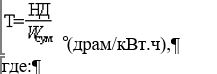
Figure 2. Departure angle
Figure 3. Ramp angle
Figure 4. Ground clearance between the axles

Figure 5. Ground clearance under one axle
1.3. Special-purpose and specialised vehicles subject to additional safety requirements
Table 2
No. | Objects of technical regulation |
1. | Truck-mounted concrete pumps |
2. | Truck mixers |
3. | Bitumen distributor trucks |
4. | Truck cranes and vehicles equipped with loader cranes |
5. | Timber trucks |
6. | Ambulances |
7. | Dump trucks and dump trailers (semi-trailers) |
8. | Bulk cement trucks |
9. | Recovery vehicles |
10. | Mobile medical units on vehicle chassis |
11. | Fire-fighting vehicles |
12. | Vehicles for emergency rescue services and the militia (police) |
13. | Vehicles for municipal services and road maintenance |
14. | Vehicles for servicing oil and gas wells |
15. | Vehicles for transporting cash and valuables |
16. | Vehicles for transporting children aged 6 to 16 years |
17. | Vehicles for transporting goods using a pole trailer |
18. | Vehicles for transporting petroleum products |
19. | Vehicles for transporting liquid foodstuffs |
20. | Vehicles for transporting liquefied petroleum gases (LPG) at pressures up to 1,8 MPa |
21. | Prisoner transport vehicles |
22. | Vehicles equipped with aerial work platforms |
23. | Van-type vehicles for transporting food products |
1.4. Classification of vehicles of categories M and N and of internal combustion engines for such vehicles into environmental classes
Emission levels and requirements ensuring compliance with the established emission levels for the various environmental classes of vehicles and internal combustion engines:
Table 3
Footnote. Table 3 as amended by Decision of the Council of the Eurasian Economic Commission No. 66 of 21.06.2019 (enters into force upon expiry of 180 calendar days from the date of its official publication).Environmental class | Categories and subgroups of vehicles and internal combustion engines | Technical requirements for vehicles and internal combustion engines |
0 | M1, M2, N1, N2 (within the scope of UN Regulation No. 83) with petrol and gas engines | UN Regulation No. 83-02 (emission level A) |
M1 with a maximum mass exceeding 3,5 t, M2, M3, N1, N2, N3 with diesel engines | UN Regulation No. 49-01 | |
M1 with a maximum mass exceeding 3,5 t, M2, M3, N2, N3 with petrol engines | CO - 85 g/kW·h, HC - 5 g/kW·h, NOx - 17 g/kW·h (9-mode test cycle) | |
diesel engines intended for installation in vehicles of categories M1 with a maximum mass exceeding 3,5 t, M2, M3, N1, N2, N3 | UN Regulation No. 49-01 | |
petrol engines intended for installation in vehicles of categories M1 with a maximum mass exceeding 3,5 t, M2, M3, N2, N3 | CO - 85 g/kW·h, HC - 5 g/kW·h, NOx - 17 g/kW·h (9-mode test cycle) | |
1 | M1, M2, N1, N2 (within the scope of UN Regulation No. 83) with petrol and gas engines and diesel engines | UN Regulation No. 83-02 (emission levels B, C, respectively) |
M1 with a maximum mass exceeding 3,5 t, M2, M3, N1, N2, N3 with gas engines and diesel engines | UN Regulation No. 49-02 (emission level A) | |
M1 with a maximum mass exceeding 3,5 t, M2, M3, N2, N3 with petrol engines | CO - 72 g/kW·h, HC - 4 g/kW·h, NOx - 14 g/kW·h (9-mode test cycle) | |
diesel engines and gas engines intended for installation in vehicles of categories M1 with a maximum mass exceeding 3,5 t, M2, M3, N1, N2, N3 | UN Regulation No. 49-02 (emission level A) | |
petrol engines intended for installation in vehicles of categories M1 with a maximum mass exceeding 3,5 t, M2, M3, N2, N3 | CO - 72 g/kW·h, HC - 4 g/kW·h, NOx - 14 g/kW·h (9-mode test cycle) | |
2 | M1, M2, N1, N2 (within the scope of UN Regulation No. 83) with petrol and gas engines and diesel engines | UN Regulation No. 83-04 (emission levels B, C, D, respectively) |
M1 with a maximum mass exceeding 3,5 t, M2, M3, N1, N2, N3 with gas engines and diesel engines | UN Regulation No. 49-02 (emission level B) | |
M1 with a maximum mass exceeding 3,5 t, M2, M3, N2, N3 with petrol engines | CO - 55 g/kW·h, HC - 2,4 g/kW·h, NOx - 10 g/kW·h (when tested in accordance with UN Regulation No. 49-04 (ESC test cycle)) | |
diesel engines and gas engines intended for installation in vehicles of categories M1 with a maximum mass exceeding 3,5 t, M2, M3, N1, N2, N3 | UN Regulation No. 49-02 (emission level B) | |
petrol engines intended for installation in vehicles of categories M1 with a maximum mass exceeding 3,5 t, M2, M3, N2, N3 | CO - 55 g/kW·h, HC - 2,4 g/kW·h, NOx - 10 g/kW·h (when tested in accordance with UN Regulation No. 49-04 (ESC test cycle)) | |
3 | M1, M2, N1, N2 (within the scope of UN Regulation No. 83) with petrol and gas engines and diesel engines | UN Regulation No. 83-05 (emission level A) |
M1 with a maximum mass exceeding 3,5 t, M2, M3, N1, N2, N3 with gas engines and diesel engines | UN Regulation No. 49-04 (emission level A) | |
M1G and M2G with a maximum mass exceeding 3,5 t, M3G, N2G, N3G with diesel engines | UN Regulation No. 96-01 | |
M1 with a maximum mass exceeding 3,5 t, M2, M3, N2, N3 with petrol engines | Paragraph 12 of Annex No. 3 to this Technical Regulation | |
diesel engines and gas engines intended for installation in vehicles of categories M1 with a maximum mass exceeding 3,5 t, M2, M3, N1, N2, N3 | UN Regulation No. 49-04 (emission level A) | |
diesel engines intended for installation in vehicles of categories M1G and M2G with a maximum mass exceeding 3,5 t, M3G, N2G, N3G | UN Regulation No. 96-01 | |
petrol engines intended for installation in vehicles of categories M1 with a maximum mass exceeding 3,5 t, M2, M3, N2, N3 | Paragraph 12 of Annex No. 3 to this Technical Regulation | |
4 | M1, M2, N1, N2 (within the scope of UN Regulation No. 83) with positive-ignition engines and diesel engines | UN Regulation No. 83-05 (emission level B) |
M1 with a maximum mass exceeding 3,5 t, M2, M3, N1, N2, N3 with gas engines and diesel engines | UN Regulation No. 49-05 (emission level B1, level of requirements for on-board diagnostics (OBD), durability and in-service conformity, and NOx control – "C") | |
M1G and M2G with a maximum mass exceeding 3,5 t, M3G, N2G, N3G with all-wheel drive, including those with a disengageable drive on one of the axles, with diesel engines | UN Regulation No. 96-02 | |
M1 with a maximum mass exceeding 3,5 t, M2, M3, N2, N3 with petrol engines | Paragraph 12 of Annex No. 3 to this Technical Regulation | |
diesel engines and gas engines intended for installation in vehicles of categories M1 with a maximum mass exceeding 3,5 t, M2, M3, N1, N2, N3 | UN Regulation No. 49-05 (emission level B1, level of requirements for on-board diagnostics (OBD), durability and in-service conformity, and NOx control – "C") | |
diesel engines intended for installation in vehicles of categories M1G and M2G with a maximum mass exceeding 3,5 t, M3G, N2G, N3G, with all-wheel drive, including those with a disengageable drive on one of the axles | UN Regulation No. 96-02 | |
petrol engines intended for installation in vehicles of categories M1 with a maximum mass exceeding 3,5 t, M2, M3, N2, N3 | Paragraph 12 of Annex No. 3 to this Technical Regulation | |
Hybrid M, N vehicles (within the scope of UN Regulation No. 49) and engines intended for installation in such vehicles | Paragraph 13 of Annex No. 3 to this Technical Regulation | |
5 | M1, M2, N1, N2 (within the scope of UN Regulation No. 83-06) with positive-ignition engines and diesel engines | UN Regulation No. 83-06, |
M1 with a maximum mass exceeding 3,5 t, M2, M3, N1, N2, N3 with gas engines and diesel engines | UN Regulation No. 49-05 (emission levels B2, C, level of requirements for on-board diagnostics (OBD), durability and NOx control – "G", "K") | |
diesel engines and gas engines intended for installation in vehicles of categories M1 with a maximum mass exceeding 3,5 t, M2, M3, N1, N2, N3 | UN Regulation No. 49-05 (emission levels B2, C, level of requirements for on-board diagnostics (OBD), durability and NOx control – "G", "K") | |
Hybrid M, N vehicles (within the scope of UN Regulation No. 49) and engines intended for installation in such vehicles | Paragraph 13 of Annex No. 3 to this Technical Regulation | |
6 | M1, N1, M2, N2 (within the scope of UN Regulation No. 83-07) with spark-ignition engines (petrol, gas) and diesel engines | UN Regulation No. 83-07 |
M1, N1, M2, N2 with a reference mass of more than 2 840 kg, M3, N3 with diesel engines, dual-fuel engines and spark-ignition engines (petrol, gas and bi-fuel (when operating on gaseous fuel)) | UN Regulation No. 49-06 | |
diesel engines, dual-fuel engines and spark-ignition engines (petrol, gas and bi-fuel (when operating on gaseous fuel)) intended for installation in vehicles of categories M1, M2, N1, N2 with a reference mass of more than 2 840 kg, M3, N3 | UN Regulation No. 49-06 |
2. Vehicle components
Table 4
Footnote. Table 4 as amended by Decisions of the Council of the Eurasian Economic Commission of 30.01.2013 No. 6 (enters into force upon expiry of 30 calendar days from the date of its official publication); of 14.10.2015 No. 78 (enters into force upon expiry of 10 calendar days from the date of its official publication); of 16.02.2018 No. 29 (enters into force upon expiry of 180 calendar days from the date of its official publication).No. | Objects of technical regulation |
1. | Positive-ignition engines |
2. | Compression-ignition engines |
3. | Gaseous fuel supply equipment (compressed natural gas – CNG, liquefied petroleum gas – LPG (or liquefied hydrocarbon gas – LPG), liquefied natural gas – LNG, dimethyl ether fuel – DME): - gas cylinder; - cylinder auxiliary equipment; - gas pressure-reducing equipment; - heat exchangers; - gas mixing devices; - gas metering devices; - solenoid valves; - filling-and-delivery equipment and control and measuring equipment; - gas filter; - flexible hoses; - fuel lines; - electronic control units |
4. | Exhaust aftertreatment systems, including replacement catalytic converters (except urea-based aftertreatment systems)* |
5. | Replacement engine exhaust systems, including silencers and resonators |
6. | Fuel tanks, filler necks and fuel tank caps |
7. | Brake pad and shoe assemblies with linings for disc and drum brakes, friction linings for drum and disc brakes* |
8. | Hydraulic brake transmission components: brake master cylinders, disc brake calipers, wheel brake cylinders of drum brakes, brake force regulators, vacuum and hydraulic boosters (assembled with brake master cylinders), hydrovacuum and pneumohydraulic boosters, warning and monitoring devices* |
9. | Pipes and hoses, including coiled hoses (including those made of polyamide 11 and 12-based material), of hydraulic brake transmission, clutch and steering drive systems* |
10. | Brake assemblies* |
11. | Parts and assemblies of mechanical brake transmissions: brake adjusting devices, parking braking system control parts (including cable assemblies with end fittings)* |
12. | Brake discs and drums * |
13. | Pneumatic brake transmission components: air treatment units (anti-freezers, moisture separators, pressure regulators), pneumatic transmission protection devices, condensate drain valves, control devices (brake valves, relay valves, trailer brake control valves, distributor valves), braking correction devices (brake force regulators, pressure-limiting valves in the front axle pneumatic transmission), coupling heads, warning and monitoring devices (pneumoelectric sensors, test connection valves)* |
14. | Pneumatic brake chambers (including those with spring brake actuators), pneumatic brake cylinders* |
15. | Compressors* |
16. | Vehicle steering assemblies and parts: steering wheels, steering gears, power steering units, hydraulic pumps, control valves and power cylinders of power steering units, steering columns, angle gearboxes, steering shafts, steering rods, intermediate steering linkage supports and arms, steering knuckle kingpins* |
17. | Motorcycle-type handlebars * |
18. | Suspension and steering ball joints |
19. | Vehicle wheels |
20. | Pneumatic tyres for passenger cars and their trailers |
21. | Pneumatic tyres for light commercial vehicles, trucks and their trailers, buses and trolleybuses |
22. | Pneumatic tyres for motorcycles, motor scooters, quadricycles and mopeds |
23. | Pneumatic tyres for temporary-use spare wheels |
24. | Retreaded pneumatic tyres for motor vehicles and their trailers |
25. | Coupling devices (drawbar couplings, fifth-wheel couplings and towing devices) |
26. | Hydraulic tipping mechanisms of dump trucks: - single-acting telescopic hydraulic cylinders; - hydraulic directional control valve with manual and remote control |
27. | Hydraulic cab-tilting mechanisms of vehicles: - hydraulic cylinders of the hydraulic cab-tilting mechanism; - pumps of the hydraulic cab-tilting mechanism |
28. | Hoses for power steering and dump truck body tipping mechanisms* |
29. | Bumpers, protective bars for motorcycles |
30. | Rear and lateral protective devices of trucks and trailers |
31. | Vehicle seats |
32. | Seat head restraints |
33. | Safety belts |
34. | Airbags |
35. | Child restraint systems |
36. | Safety glazing |
37. | Rear-view mirrors |
38. | Windscreen wipers and spare parts thereof (gear motors, wiper blades) * |
39. | Headlamp cleaners and spare parts thereof (gear motors) |
40. | Vehicle passing-beam and driving-beam headlamps |
41. | Filament lamps for headlamps and lamps |
42. | Retro-reflecting devices (retro-reflectors) |
43. | Rear registration plate lamps |
44. | Direction indicators |
45. | Position lamps and end-outline marker lamps, stop lamps |
46. | Front fog lamps |
47. | Lighting and light-signalling devices of motorcycles and quadricycles |
48. | Vehicle reversing lamps |
49. | HSB halogen sealed-beam headlamps |
50. | Rear fog lamps |
51. | Headlamps for mopeds |
52. | Headlamps for motorcycles |
53. | Warning lamps |
54. | Motorcycle headlamps with HS halogen lamps |
55. | Passing-beam and driving-beam headlamps for mopeds |
56. | Parking lamps |
57. | Moped headlamps with HS2 halogen lamps |
58. | Daytime running lamps |
59. | Side-marker lamps |
60. | Headlamps with gas-discharge light sources |
61. | Gas-discharge light sources |
62. | Audible warning devices |
63. | Speedometers, their sensors and instrument clusters incorporating speedometers |
64. | Speed limitation devices |
65. | Technical means for monitoring drivers' compliance with driving, work and rest periods (tachographs) |
66. | Alarm systems, anti-theft and security devices for vehicles |
67. | Rear marking plates for slow-moving vehicles |
68. | Rear marking plates for heavy and long vehicles |
69. | Retro-reflective marking for heavy and long vehicles |
70. | Warning triangles (advance warning triangles) |
71. | Starter batteries |
72. | Wiring harnesses |
73. | High-voltage ignition cables |
74. | Emergency condition indicators and sensors * |
75. | Turbochargers * |
76. | Cylinder-piston group parts, valve train parts, crankshafts, bearing shells, connecting rods * |
77. | Fuel injection systems of positive-ignition engines and their replaceable elements * |
78. | Air cleaners for internal combustion engines and their replaceable elements |
79. | Oil filters and their replaceable elements |
80. | Diesel engine fuel filters and their replaceable elements |
81. | Fuel filters for positive-ignition engines and their replacement elements |
82. | High-pressure fuel pumps, fuel feed pumps, plunger pairs, injectors and injector nozzles for diesel engines* |
83. | Heat exchangers and thermostats |
84. | Pumps for liquid cooling systems |
85. | Clutches and their parts (discs, cylinders, hoses)* |
86. | Cardan (propeller) shafts, drive shafts, non-constant-velocity and constant-velocity joints* |
87. | Driving axles with differential, assembled; axle shafts * |
88. | Suspension elastic elements (leaf springs, coil springs, suspension torsion bars, anti-roll bars, pneumatic elastic elements)* |
89. | Damping elements of the suspension (shock absorbers, shock absorber struts and shock absorber strut cartridges) and of the steering linkage* |
90. | Suspension guiding components (control arms, reaction rods and their pins, rubber-metal joints, support bearings and bushings, suspension travel limiters)* |
91. | Hub caps and decorative wheel covers. Wheel fasteners. Wheel balancing weights.* |
92. | Ignition system products for positive-ignition engines (distributors, sensor-distributors, ignition coils, ignition modules, electronic switching units, controllers, sensors, contact breakers). |
93. | Spark plugs; glow plugs |
94. | Electric generators, rectifier units, electric motors (for fan drives, petrol pumps, windscreen washers, window regulators, heaters, mirror adjustment, door locking) |
95. | Starters, starter drives and starter relays |
96. | Switching, protective and installation equipment for power supply circuits of starting, ignition, external lighting and audible warning devices, windscreen wipers and fuel supply systems; detachable connectors * |
97. | Decorative parts of the body and bumpers, radiator grilles, headlamp visors and rims * |
98. | Handles (external and internal) and door hinges on the side surfaces of the body, external side push-buttons for opening doors and luggage compartments* |
99. | Door locks * |
100. | Protective rubber and rubber-metal parts (caps, boots, sealing rings, cups for hydraulic brake and clutch actuation, boots for steering joints, suspension joints and propeller shaft joints)* |
101. | Gaskets for cylinder heads, manifolds and gas-fuel equipment; sealing rings * |
102. | Clutch release units, wheel hubs, wheel axle shafts, including those with bearings assembled; bearings for clutch release units, wheel hubs and wheel axle shafts * |
103. | Air-liquid heaters; integral coolers, heater-coolers* |
104. | Independent automatic air and liquid heaters powered by the vehicle on-board electrical system and running on liquid or gaseous fuel, including pre-start heaters |
105. | Hydraulic and mechanical jacks* |
106. | Chains and chain tensioners for internal combustion engines* |
107. | Fan V-belts and synchronous poly-V belts for motor vehicle engines, toothed timing belts for motor vehicle engines |
108. | Rubber-fabric dished diaphragms and membranes for vehicles* |
109. | Protective helmets for drivers and passengers of motorcycles and mopeds |
110. | Luggage carriers for motor vehicles* |
111. | Partition systems for protecting passengers against displacement of luggage |
112. | Materials for interior trim and seats of vehicles of category M3, Classes II and III* |
113. | External antennas for radio, television and satellite navigation systems |
114. | Adaptive front-lighting systems |
115. 116. | Spray-suppression devices* Anti-skid studs* |
117. | Satellite navigation equipment |
118. | Emergency call device |
* – until 1 July 2017, the manufacture and placing on the market of the specified products in the territory of the Republic of Kazakhstan are permitted without documents on mandatory conformity assessment and without marking with the national conformity mark (mark of circulation on the market).
ANNEX No. 2
to the Technical Regulation
of the Customs Union
"On the Safety of Wheeled
Vehicles"
(TR CU 018/2011)
LIST
of requirements established for types of vehicles (chassis) placed on the market
Footnote. Annex No. 2 as amended by Decisions of the Council of the Eurasian Economic Commission of 16.02.2018 No. 29 (enters into force upon expiry of 180 calendar days from the date of its official publication); of 15.04.2022 No. 54 (enters into force upon expiry of 30 calendar days from the date of its official publication); of 17.10.2022 No. 167 (enters into force upon expiry of 10 calendar days from the date of its official publication).
1. The list of requirements established for types of vehicles (chassis) placed on the market is given in the table.
2. The requirements apply in accordance with the scope and taking into account the transitional provisions established in the UN Regulations (UN Global Technical Regulations).
3. The requirements are introduced from 1 January of the year specified in the table. If no date of introduction is specified, the requirements apply from the date of entry into force of this Technical Regulation. If the UN Regulations (UN Global Technical Regulations) provide for later dates of introduction of requirements than the dates set out in the table, the dates of introduction of requirements established by the UN Regulations (UN Global Technical Regulations) apply.
4. The expiry date of the requirements (if established) is 31 December of the year specified in the table.
5. Alternative application of higher-level requirements before the dates set out in the list of requirements is permitted.
6. In the conformity assessment of vehicles (chassis) belonging to a type that has not previously undergone conformity assessment under this Technical Regulation or under the national procedures of the Customs Union Member States, as well as in the renewal of previously issued Vehicle (Chassis) Type Approvals taking into account subparagraph 5 of paragraph 65 of this Regulation or their extension taking into account subparagraph 2 of paragraph 60 of this Regulation, the UN Regulations with the series of amendments specified in the table apply, in the version in force at the time of registration of the Vehicle (Chassis) Type Approval in the register, taking into account their transitional provisions.
In the extension of previously issued Vehicle (Chassis) Type Approvals taking into account subparagraph 1 of paragraph 60 of this Regulation, the level of requirements is determined as at the date of issue of the original documents, except for the requirements for emissions.
7. If a communication concerning UN approval of a vehicle type under UN Regulations is submitted as supporting evidence for the requirements of Annex No. 2, submission of copies of communications concerning approval of individual component types that fall under these UN Regulations and are specified in the communication concerning UN approval of the vehicle type is not mandatory.
8. Conformity assessment against the requirements specified in the table is carried out in the form of mandatory certification.
Table
Footnote. Table as amended by Decisions of the Council of the Eurasian Economic Commission of 30.01.2013 No. 6 (enters into force upon expiry of 30 calendar days from the date of its official publication); of 14.10.2015 No. 78 (enters into force upon expiry of 10 calendar days from the date of its official publication); of 16.02.2018 No. 29 (enters into force upon expiry of 180 calendar days from the date of its official publication); of 15.04.2022 No. 54 (enters into force upon expiry of 30 calendar days from the date of its official publication).
No. |
Elements and properties of objects of technical regulation for which requirements are established |
Applicability by vehicle category |
Documents, conformity with which ensures compliance with the requirement |
Note |
1. |
Passing-beam and driving-beam headlamps |
M, N, L |
UN Regulation No. 1-02 |
20) |
2. |
Retro-reflectors |
M, N, O, L |
UN Regulation No. 3-02 | |
3. |
Devices for the illumination of the rear registration plate |
M, N, O |
UN Regulation No. 4-00 | |
4. |
Direction indicators |
M, N, O, L |
UN Regulation No. 6-01 | |
5. |
Position lamps, stop lamps |
M, N, O, L |
UN Regulation No. 7-02 |
4) |
6. |
Passing-beam and driving-beam headlamps |
M, N, L |
UN Regulation No. 8-05 |
20) |
7. |
External noise |
L2, L4, L5, L6, L7 |
UN Regulation No. 9-06 | |
8. |
Resistance to external sources of electromagnetic radiation and electromagnetic compatibility |
M, N, O, L |
UN Regulation No. 10-03 | |
9. |
Door latches and hinges |
M1, N1 |
UN Regulation No. 11-02 |
4), 16), 23), 33) |
M1, N1 |
UN Regulation No. 11-03 |
2), 4), 16), 23), 33) | ||
10. |
Occupant protection of the steering equipment |
M1, N1 |
UN Regulation No. 12-03 |
16), 22) |
11. | Performance of braking systems | M1, N1 | UN Regulation No. 13H-00 | 24) |
M2, M3, N, O | UN Regulation No. 13-10 (until 2017) | |||
M2, M3, N, O | UN Regulation No. 13-11 (from 2018) |
35), 46) | ||
12. |
Safety-belt anchorages |
M, N, L6, L7 |
UN Regulation No. 14-07 |
4), 18), 23) |
13. |
Equipping of vehicles with restraint systems |
M, N, L6, L7 |
UN Regulation No. 16-06 |
4), 18), 23) |
14. |
Strength of seats and their anchorages |
M1, M2, M3, N1, N2, N3 |
UN Regulation No. 17-08 |
16), 19), 23) |
15. |
Protection of the vehicle against unauthorised use |
M, N, L6, L7 |
UN Regulation No. 18-02 |
4), 23) |
M2, M3, N2, N3, L6, L7 |
UN Regulation No. 18-03 |
2), 4), 23) | ||
16. |
Front fog lamps |
M, N, L3, L4, L5, L7 |
UN Regulation No. 19-03, |
4), 20) |
17. |
Passing-beam and driving-beam headlamps |
M, N, L |
UN Regulation No. 20-03 |
20) |
18. |
Occupant protection of interior fittings |
M1 |
UN Regulation No. 21-01 |
2), 16), 23) |
UN Regulation No. 21-01 |
16), 23) | |||
19. |
Reversing lamps |
M, N, O |
UN Regulation No. 23-00 | |
20. |
Emissions |
L6, L7, M, N (with diesel engines) |
UN Regulation No. 24-03 | |
21. |
Seat head restraints |
M1, M2 (with a technically permissible maximum laden mass of up to 3,5 t), N1 |
UN Regulation No. 25-04 |
11), 23) |
22. |
Injury protection of external projections |
M1 |
UN Regulation No. 26-03 |
4), 16), 23) |
23. |
Equipping with audible warning devices |
M, N, L3, L4, L5, L6, L7 |
UN Regulation No. 28-00 |
23) |
24. |
Protective properties of cabs |
N |
UN Regulation No. 29-02 | 23), 40), 43) |
25. |
Equipping with tyres |
M, N, O, L6, L7 |
UN Regulation No. 30-02 |
20) |
26. |
Passing-beam and driving-beam headlamps |
M, N |
UN Regulation No. 31-02 |
20) |
27. |
Fire safety |
M1 |
UN Regulation No. 34-01 | 23) |
M, N, O |
UN Regulation No. 34-02 |
2), 23) | ||
M, N, O |
UN Regulation No. 34-02 | 23) | ||
28. |
Arrangement of control pedals |
M1 |
UN Regulation No. 35-00 | 16), 23) |
29. |
General safety requirements for vehicles with a capacity of more than 22 passengers |
M2, M3 |
UN Regulation No. 36-03 |
8), 23), 27), 38) |
30. |
Rear fog lamps |
M, N, O, L3, L4, L5, L7 |
UN Regulation No. 38-00 |
4) |
31. |
Speed measuring devices |
M, N, L3, L4, L5, L7 |
UN Regulation No. 39-00 |
4) |
32. |
Emissions |
L3, L4, L5, L6, L7 |
UN Regulation No. 40-01 | |
33. |
External noise |
L3 |
UN Regulation No. 41-03 | |
34. |
Equipping with safety glazing |
M, N, O, L6, L7 |
UN Regulation No. 43-00 |
3), 4), 22) |
35. |
Headlamp cleaning devices |
M, N |
UN Regulation No. 45-01 |
20), 26) |
36. |
Equipping with devices for indirect vision |
M, N, L6, L7 |
UN Regulation No. 46-02 | 44) |
37. |
Emissions |
L1, L2 |
UN Regulation No. 47-00 | |
38. | Equipping with lighting and light-signalling devices | M, N, O | UN Regulation No. 48-03 | 17), 31), 45) |
UN Regulation No. 48-04 | 2), 17), 31), 42), 45) | |||
39. |
Emissions |
M, N with gas engines and diesel engines |
UN Regulation No. 49-05 (emission level B1, level of requirements | |
M1 – (until 2015) |
29) | |||
M1G, M2, M3, N – (until 2017) |
29) | |||
M1 – (from 2015 until 2016) |
28) | |||
M1G, M2, M3, N – (until 2018) |
28) | |||
UN Regulation No. 49-05 (emission levels B2, C, level of requirements | ||||
M1 – (from 2016) |
29) | |||
M1G, M2, M3, N – (from 2018) |
29) | |||
M1 – (from 2017) |
28) | |||
M1G, M2, M3, N – (from 2019) |
28) | |||
(from 2016) |
2) | |||
40. |
Front and rear position lamps, stop lamps, direction indicators, rear registration plate lamps |
L |
UN Regulation No. 50-00 | |
41. |
External noise |
M, N |
UN Regulation No. 51-02 |
6), 14), 23), 34) |
42. |
General safety requirements for vehicles with a capacity of not more than 22 passengers |
M2, M3 |
UN Regulation No. 52-01 | 9), 23), 27), 38) |
43. |
Fitting of lighting and light-signalling devices |
L3 |
UN Regulation No. 53-01 | |
44. |
Fitting of tyres |
M, N, O |
UN Regulation No. 54-00 |
20) |
45. |
Fitting of coupling devices |
M, N, O |
UN Regulation No. 55-01 |
20) |
46. |
Passing-beam and driving-beam headlamps |
L1, L2, L6 |
UN Regulation No. 56-01 |
20) |
47. |
Passing-beam and driving-beam headlamps |
L3, L4, L5, L7 |
UN Regulation No. 57-02 |
20) |
48. |
Fitting of rear underrun protective devices to vehicles for the carriage of goods |
N2, N3, O3, O4 |
UN Regulation No. 58-02 |
31) |
49. |
Controls of mopeds and two-wheeled motorcycles | L1, L3, , L6, L7 |
UN Regulation No. 60-00 | 39) |
50. |
Injury protection of external projections |
N |
UN Regulation No. 61-00 | 23) |
51. |
Protection of the vehicle against unauthorised use | L |
UN Regulation No. 62-00 | 39) |
52. |
External noise |
L1 |
UN Regulation No. 63-01 | |
53. |
Fitting of temporary-use tyres |
M1, N1 |
UN Regulation No. 64-02 |
20) |
54. |
Tyre pressure monitoring systems |
M1 |
UN Regulation No. 64-02 |
2), 20), 25) |
55. |
Special warning lamps |
M, N, L |
UN Regulation No. 65-00 |
20) |
56. |
Strength of the superstructure |
M2, M3 |
UN Regulation No. 66-02 | |
57. |
Vehicles and fuel systems using liquefied petroleum gas (LPG) |
M, N |
UN Regulation No. 67-01 | |
58. |
Passing-beam and driving-beam headlamps |
L3, L4, L5, L7 |
UN Regulation No. 72-01 |
20) |
59. |
Fitting of lateral protection devices to vehicles for the carriage of goods |
N2, N3, O3, O4 |
UN Regulation No. 73-00 |
31) |
60. |
Fitting of lighting and light-signalling devices |
L1 |
UN Regulation No. 74-01 | |
61. |
Fitting of tyres |
L |
UN Regulation No. 75-00 |
20) |
62. |
Passing-beam and driving-beam headlamps |
L1, L2, L6 |
UN Regulation No. 76-01 |
20) |
63. |
Parking lamps |
M, N |
UN Regulation No. 77-00 |
20) |
64. |
Braking performance |
L |
UN Regulation No. 78-03 | |
65. |
Steering equipment |
M, N, O |
UN Regulation No. 79-01 |
4) |
66. |
Strength of seats and their anchorages |
M2, M3 |
UN Regulation No. 80-01 |
5), 19) |
67. |
Fitting of devices for indirect vision | L |
UN Regulation No. 81-00 | 39) |
68. |
Passing-beam and driving-beam headlamps |
L1, L2, L6 |
UN Regulation No. 82-01 |
20) |
69. |
Emissions |
M1, M2, N1, N2 with positive-ignition engines and diesel engines |
UN Regulation No. 83-05 (emission level B) (environmental class 4) | |
M1 – (2015) | 29), 41) | |||
M1G, M2, N1, N2 – (until 2017) |
29) | |||
M1 – (from 2015 to 2016) |
28) | |||
M1G, M2, N1, N2 – (until 2018) |
28) | |||
UN Regulation No. 83-06 (environmental class 5) | ||||
M1 – (from 2016) |
29) | |||
M1G, M2, N1, N2 – (from 2018) |
29) | |||
M1 – (from 2017) |
28) | |||
M1G, M2, N1, N2 – (from 2019) |
28) | |||
70. |
Daytime running lamps |
M, N |
UN Regulation No. 87-00 |
20) |
71. |
Fitting of tyres |
L1 |
UN Regulation No. 88-00 | |
72. |
Fitting of maximum speed limitation devices |
M, N |
UN Regulation No. 89-00 |
20) |
73. |
Side-marker lamps |
M, N, O |
UN Regulation No. 91-00 | |
74. |
Fitting of front underrun protective devices to vehicles for the carriage of goods |
N2, N3 |
UN Regulation No. 93-00 | |
75. |
Protection of the driver and passengers in the event of a frontal collision |
M1 |
UN Regulation No. 94-01 |
1), 16), 22) |
76. |
Protection of the driver and passengers in the event of a lateral collision |
M1 |
UN Regulation No. 95-02 |
1), 16), 22) |
77. |
Emissions | M1G with a maximum mass exceeding 3,5 t, M2G, M3G, N2G, N3G with diesel engines, self-propelled chassis intended exclusively for mounting crane installations |
UN Regulation No. 96-02 (environmental class 4) | |
(2017) |
29), 30) | |||
(until 2018) |
28), 30) | |||
78. |
Passing-beam and driving-beam headlamps | M, N, L3, , L6, L7 |
UN Regulation No. 98-00 |
20) |
79. | Safety of vehicles with an electric power train | M, N | UN Regulation No. 100-01 | |
80. |
Fuel consumption and carbon dioxide emissions. Electric energy consumption and range of electrically driven vehicles |
M1, N1 |
UN Regulation No. 101-01 |
2), 16), 22) |
81. |
Fitting of close-coupling devices |
N2, N3, O3, O4 |
UN Regulation No. 102-00 |
20) |
82. |
Retro-reflective marking |
N2, N3, O3, O4 |
UN Regulation No. 104-00 | |
83. |
General safety requirements for passenger vehicles |
M2, M3 |
UN Regulation No. 107-03 | 2), 10), 23) |
84. |
Vehicles and compressed natural gas (CNG) fuel systems |
M, N |
UN Regulation No. 110-00 | |
85. |
Passing-beam and driving-beam headlamps |
M, N |
UN Regulation No. 112-00, |
20) |
86. |
Passing-beam and driving-beam headlamps |
L |
UN Regulation No. 113-00 |
20) |
87. |
Protection of the vehicle against unauthorised use |
M1, N1 |
UN Regulation No. 116-00 |
2), 13), 16), 21), 23) |
88. |
Tyre rolling noise level |
M, N, O |
UN Regulation No. 117-02, stage 1 |
36) |
M, N, O |
UN Regulation No. 117-02, stage 2 |
36) | ||
89. |
Tyre wet grip |
M1, N1, O1, O2 |
UN Regulation No. 117-02 |
36) |
90. |
Tyre rolling resistance |
M, N, O |
UN Regulation No. 117-02, stage 1 | |
91. |
Fire safety properties of the interior |
M3 (Classes II and III) |
UN Regulation No. 118-00 |
2) |
UN Regulation No. 118-00 | ||||
92. |
Cornering lamps |
M1 |
UN Regulation No. 119-00 |
20) |
93. |
Vehicle controls - identification |
M, N, L6, L7 |
UN Regulation No. 121-00 |
2), 4), 16) |
UN Regulation No. 121-00 |
4), 16) | |||
94. |
Heating systems |
M, N |
UN Regulation No. 122-00 | 23) |
95. |
Adaptive front-lighting systems (AFS) |
M, N |
UN Regulation No. 123-00 |
20) |
96. |
Forward field of vision |
M1 |
UN Regulation No. 125-00 |
7), 16), 22), 23) |
97. |
Door locks and hinges |
N2, N3 |
UN Global Technical Regulation (UN GTR) No. 1 | 2), 23) |
98. |
Pedestrian protection |
M1, N1 |
UN Global Technical Regulation (UN GTR) No. 9 |
2), 15), 22) |
99. |
Installation of lighting and light-signalling devices |
L2, L4, L5, L6, L7 |
Paragraph 1 of Annex No. 3 to this Technical Regulation |
17) |
100. |
Interior noise |
M, N |
Paragraph 2 of Annex No. 3 to this Technical Regulation | 23) |
101. |
Content of harmful (polluting) substances in the air of the vehicle occupant compartment |
M, N |
Paragraph 3 of Annex No. 3 to this Technical Regulation | |
102. |
Stability |
M, N, O |
Paragraph 4 of Annex No. 3 to this Technical Regulation |
12), 16) 46) |
103. |
Forward field of vision |
M2, M3, N |
Paragraph 5 of Annex No. 3 to this Technical Regulation |
7), 22), 23) |
104. |
Ventilation, heating and air-conditioning |
M, N |
Paragraph 6 of Annex No. 3 to this Technical Regulation | 23) |
105. |
Windscreen defrosting and demisting systems |
M1 |
Paragraph 7 of Annex No. 3 to this Technical Regulation | 16), 23) |
106. |
Windscreen wipers and washers |
M1 |
Paragraph 8 of Annex No. 3 to this Technical Regulation | 16), 23) |
107. |
Protection against spray from the wheels |
N, O |
Paragraph 9 of Annex No. 3 to this Technical Regulation | 2), 23), 32) |
M1 |
Paragraph 10 of Annex No. 3 to this Technical Regulation | 2), 16), 23) | ||
108. |
Industrial radio interference from trolleybuses |
M3 (trolleybuses) |
Paragraph 11 of Annex No. 3 to this Technical Regulation | |
109. |
Emissions |
M1 with a maximum mass exceeding 3,5 t, M2, M3, N2, N3 with petrol engines |
Paragraph 12 of Annex No. 3 to this Technical Regulation (environmental class 4) | |
110. |
Emissions |
Hybrid M, N (within the scope of UN Regulation No. 49) |
Paragraph 13 of Annex No. 3 to this Technical Regulation (environmental class 4) | |
(2015) |
29) | |||
(from 2015 to 2016) |
28) | |||
Paragraph 13 of Annex No. 3 to this Technical Regulation (environmental class 5) | ||||
(from 2016) |
29) | |||
(from 2017) |
28) | |||
111. |
Weight limits applicable to vehicles |
M, N, O |
Paragraph 14 of Annex No. 3 to this Technical Regulation | |
112. |
Additional requirements for vehicles intended for persons with reduced mobility |
M1, N1 |
Paragraph 15 of Annex No. 3 to this Technical Regulation | |
113. |
Fitting with an emergency call device |
M1 not falling within the scope of UN Regulations Nos. 94 and 95; N1 not falling |
Paragraph 16 of Annex No. 3 to this Technical Regulation |
2) |
114. |
Fitting with an emergency call system |
M1 falling within the scope of UN Regulations Nos. 94 and 95; N1 falling |
Paragraph 17 of Annex No. 3 to this Technical Regulation (from 2015) |
2) |
Notes:
Footnote. The Note as amended by Decisions of the Council of the Eurasian Economic Commission of 30.01.2013 No. 6 (enters into force upon expiry of 30 calendar days from the date of its official publication); of 14.10.2015 No. 78 (enters into force upon expiry of 10 calendar days from the date of its official publication); of 16.02.2018 No. 29 (enters into force upon expiry of 180 calendar days from the date of its official publication); of 15.04.2022 No. 54 (enters into force upon expiry of 30 calendar days from the date of its official publication); of 17.10.2022 No. 167 (enters into force upon expiry of 10 calendar days from the date of its official publication).1) The requirements apply to vehicle types for which the application for conformity assessment was first submitted after 4 January 2008.
2) The requirements apply to vehicle (chassis) types that have not undergone conformity assessment against this Technical Regulation, or at national level in the Member States of the Customs Union, before the requirements were introduced.
3) The requirements for quadricycles apply if glazing is fitted.
4) The requirements do not apply to quadricycles with motorcycle-type seating.
5) As an alternative, UN Regulation No. 17 may be applied to vehicles of category M2.
6) UN Regulation No. 51-02 applies in the version without Supplement 5.
7) The requirements do not apply to vehicles with bodies whose production started before 1 January 1977.
8) For specialised passenger vehicles, buses of categories M2G and M3G, buses for funeral services, and vehicles of categories M2 and M3 with a reduced number of seats, the requirements of paragraphs 5.1, 5.3, 5.6.1.1, 5.7.5-5.7.8 and 5.10 of UN Regulation No. 36-03 do not apply. In this case, an entry restricting the use of such vehicles for the commercial carriage of passengers is made in the "Vehicle Type Approval".
9) For specialised passenger vehicles, buses of categories M2G and M3G, buses for funeral services, and vehicles of categories M2 and M3 with a reduced number of seats, the requirements of paragraphs 5.1, 5.3, 5.6.1.1, 5.6.3.1, 5.7.1.1-5.7.1.7, 5.7.5-5.7.8, 5.9 and 5.10 of UN Regulation No. 52-01 do not apply. In this case, an entry restricting the use of such vehicles for the commercial carriage of passengers is made in the "Vehicle Type Approval".
10) For specialised passenger vehicles, buses of categories M2G and M3G, buses for funeral services, and vehicles of categories M2 and M3 with a reduced number of seats, the requirements of paragraphs 7.2, 7.6.1.1, 7.6.3.1, 7.7.1.1-7.7.1.7, 7.7.5-7.7.8, 7.11 and 7.12 of Annex 3 to UN Regulation No. 107 do not apply. In this case, an entry restricting the use of such vehicles for the commercial carriage of passengers is made in the "Vehicle Type Approval".
11) Supporting evidence is accepted
in respect of seats, if the seats were tested together with head restraints.
12) In the conformity assessment, communications concerning UN approval of the vehicle type under UN Regulation No. 111 are recognised.
13) If communications concerning UN approval of the vehicle type under UN Regulation No. 116 are submitted, the communication concerning UN approval of the vehicle type under UN Regulation No. 18 is not required.
14) For all-wheel-drive vehicles of categories M2G, M3G, N2G and N3G, the limit values may be exceeded by 3 dB (A) during drive-by measurements.
15) After their entry into force, the UN Regulations on pedestrian protection apply as an alternative to UN GTR No. 9.
16) For motor caravans, ambulances and hearses of categories M1, M2 and M3, the scope of applicable requirements must correspond to the scope of requirements applicable to the base vehicle.
17) Optional lighting and light-signalling devices, if fitted to the vehicle, must comply with the applicable provisions of the UN Regulations.
18) Vehicles of categories M1 and N, and vehicles of categories M2 and M3 of Classes III and B, are fitted with safety belts. Other vehicles of categories M2 and M3 are fitted with safety belts if they are used for the carriage of passengers on intercity routes.
19) The requirements apply depending on the type of seats.
20) Applies if fitted to the vehicle.
21) In the conformity assessment, communications concerning UN approval of the vehicle type under UN Regulation No. 97 are recognised.
22) The requirements do not apply to vehicles fitted with armour protection whose conformity with regulatory technical requirements has been confirmed in accordance with the established procedure.
23) For vehicles fitted with armour protection whose conformity with the legislation of a Member State of the Eurasian Economic Union has been confirmed in accordance with the established procedure, deviations from the established requirements are permitted if the design features of such a vehicle do not allow these requirements to be met in full.
24) For vehicles of a type that has not undergone conformity assessment against the requirements of this Technical Regulation or the legislation of a Member State of the Eurasian Economic Union, fitting electronic stability control (ESC) systems and brake assist systems is mandatory. Conformity assessment of vehicles of category N1 against UN Regulation No. 13-11 is permitted.
From 1 January 2016, fitting anti-lock braking systems is mandatory for vehicles not covered by the first subparagraph of this note. Fitting such vehicles with electronic stability control (ESC) systems and brake assist systems is optional.
This requirement does not apply to vehicles of category N1G or to vehicles fitted with armour protection whose conformity with the legislation of a Member State of the Eurasian Economic Union has been confirmed in accordance with the established procedure.
25) Fitting tyre pressure monitoring systems is mandatory for vehicle types that have not undergone conformity assessment against this Technical Regulation, or at national level in the Member States of the Customs Union, before the requirements were introduced.
26) Mandatory application is governed by UN Regulation No. 48.
27) UN Regulation No. 107-03 may be applied as an alternative to UN Regulations No. 36-03 and No. 52-01.
28) The requirements apply to vehicles manufactured using base vehicles or chassis that have been placed on the market and are produced by other manufacturers.
29) The requirements apply to all vehicles, except vehicles covered by notes 2) and 28).
30) The requirements apply to vehicles with all-wheel drive, including vehicles with disconnectable drive on one of the axles, and to off-road vehicles of category N3G without all-wheel drive (except those classified under CU Customs Tariff Number 8701), previously certified in the National Certification Systems against the technical emission standards set out in UN Regulation No. 96-02.
31) Exemptions are permitted for special-purpose vehicles if their special intended purpose prevents full compliance with the requirement. In this case, the applicant provides the certification body with sufficient evidence that, due to the special intended purpose, the requirements cannot be met in full.
32) For vehicles of categories N1 and N2 with a technically permissible maximum laden mass not exceeding 7,5 t, and for vehicles of categories O1 and O2, the requirements of paragraph 10 of Annex No. 3 to this Technical Regulation may be applied as an alternative.
33) The requirements for sliding doors apply from 1 January 2016.
34) In the conformity assessment, the maximum power values must be obtained by measurements in accordance with the procedure set out in UN Regulation No. 85-00 (with Supplements 1-5). This must be confirmed by a communication concerning UN approval or by a declaration of conformity adopted under declaration scheme 3d. Details of these documents are given in the "Vehicle Type Approval". The declaration scheme is described in Annex No. 19 to this Technical Regulation.
35) For vehicles of category N1 of a type that has not undergone conformity assessment against the requirements of this Technical Regulation or the legislation of a Member State of the Eurasian Economic Union, fitting electronic stability control (ESC) systems is mandatory. For other vehicles of category N1, the requirement for mandatory fitting of electronic stability control (ESC) systems applies from 1 January 2018.
This requirement does not apply to vehicles of category N1G or to vehicles fitted with armour protection whose conformity with the legislation of a Member State of the Eurasian Economic Union has been confirmed in accordance with the established procedure.
36) A test report under EU Directive 92/23/EEC, as amended by Directives 2001/43/EC and 2005/11/EC, may be submitted as supporting evidence. To identify tyres placed on the market, the numbers of the type approval communications under the said Directive are entered in the documents attesting conformity with the requirements of this Technical Regulation.
37) The requirements apply to vehicles used for the commercial carriage of passengers, to vehicles specially designed for the carriage of children aged 6 to 16 years, to vehicles for the carriage of dangerous goods, municipal solid waste and refuse (refuse collection vehicles), and to towing vehicles used to tow trailers carrying dangerous goods.
38) For vehicles designed for the carriage of persons with reduced mobility, the requirements of Annex 8 to UN Regulation No. 107-03 also apply.
39) The requirements apply to quadricycles with motorcycle-type seating.
40) At the applicant's discretion, conformity with UN Regulation No. 29-03 may be confirmed, except for vehicles outside the scope of UN Regulation No. 29-03.
41) The requirements of environmental class 5 do not apply to vehicles of category M1 fitted with armour protection whose technically permissible maximum laden mass exceeds the limit set in the scope of UN Regulation No. 83-06, provided that the base vehicle meets the applicable requirements of environmental class 5.
42) Where a communication concerning UN approval of a vehicle type provided for by UN Regulation No. 48-03 is available, the requirements of that UN Regulation apply. This includes vehicles manufactured on the basis of, or using, the chassis of other vehicles for which such a communication concerning UN approval is available. UN Regulation No. 48-03 applies to special armoured vehicles used in law enforcement.
43) The requirements do not apply to self-propelled crane units in which the boom and the hook-securing cables structurally protect the cab.
44) For special armoured vehicles used in law enforcement, only main Class II mirrors are mandatory. The requirement that the position of the exterior mirror on the driver's side be adjustable from inside the vehicle with the door closed does not apply.
45) For a vehicle fitted with armour protection whose compliance with regulatory technical requirements has been confirmed in accordance with the established procedure, all mandatory lighting devices must be installed and the requirements for their angles of visibility must be met.
46) until 31 December 2023 inclusive, vehicles of categories M3, N2, N3, O3, O4 manufactured in the territory of the Republic of Belarus may be placed without electronic stability control (ESC) systems.
ANNEX No. 3
to the Technical Regulation
of the Customs Union
"On the Safety of Wheeled
Vehicles"
(TR CU 018/2011)
Technical requirements for individual elements and
properties of objects of technical regulation for conformity
assessment of vehicle (chassis) types
Footnote. Annex No. 3 as amended by Decision of the Council of the Eurasian Economic Commission No. 29 of 16.02.2018 (enters into force 180 calendar days after the date of its official publication).
1. Requirements for three- and four‑wheeled motor vehicles regarding the number, position, characteristics and operation of lighting and light‑signalling devices
1.1. Lighting and light-signalling devices must be installed so that, under normal conditions of operation and the vibration to which they may be subjected, they retain the characteristics prescribed by paragraph 1 of this Annex, and so that the vehicle meets the requirements of paragraph 1 of this Annex.
1.2. Driving-beam headlamps, passing-beam headlamps and fog lamps must be installed so that the direction of the light beams can be adjusted.
1.3. The reference axes of all lighting and light-signalling devices installed on the vehicle must be parallel to the ground plane of the vehicle on the road. In addition, for side retro-reflectors these axes must be perpendicular to the median longitudinal plane of the vehicle, and for all other signalling devices they must be parallel to it.
A tolerance of ±3о is permitted in each direction. In addition, any specific technical specifications for installation provided by the manufacturer of the lighting and light-signalling devices must be observed.
1.4. The height and orientation of the lamps are checked with the vehicle in unladen condition, standing on a flat, horizontal surface. The median longitudinal plane of the vehicle must be vertical, and the steering equipment must be in the straight-ahead position. The tyre pressure must correspond to the value prescribed by the manufacturer.
1.5. Lamps of the same pair that have the same function must:
1.5.1. be installed on the vehicle symmetrically in relation to the median longitudinal plane;
1.5.2. be symmetrical to each other in relation to the median longitudinal plane;
1.5.3. meet the same colorimetric requirements;
1.5.4. have substantially identical photometric characteristics.
1.6. Unless otherwise specified below in this section, lamps with different functions may be independent, or grouped, combined or reciprocally incorporated in the same device, provided that each lamp meets the requirements applicable to it.
1.7. No lamp may be flashing, except direction indicators and the hazard warning signal.
1.8. No red light may be visible from the front and no white light from the rear, except the reversing lamp.
1.9. The functional wiring diagram must ensure that the front and rear position lamps and the rear registration plate lamp can be switched on and off simultaneously.
1.10. The functional wiring diagram must ensure that the driving-beam lamps, the passing-beam lamps and the front fog lamp can be switched on only if the lamps referred to in paragraph 1.9 are also switched on. However, this condition is not mandatory for driving-beam or passing-beam lamps whose light signals are intended for repeated, brief switching on and off of the driving beam or passing beam, or for brief alternate switching of the passing beam and driving beam.
1.11. Tell-tales
1.11.1. Each tell-tale must be clearly visible to the driver.
1.11.2. The circuit-closed tell-tale may be replaced by an operating tell-tale.
1.12. Colours of lamps
Lamps, headlamps, direction indicators and retro-reflectors must have the colours specified in Table 1.1.
Table 1.1.
Name of lamp | Colour |
- driving-beam and passing-beam lamps, rear registration plate lamp and front position lamp | white |
- direction indicator, hazard warning signal, non-triangular side retro-reflector | amber |
- stop lamp, rear position lamp, non-triangular rear retro-reflector, rear fog lamp | red |
- front fog lamp | white or selective yellow, less saturated |
Note: The definitions of lamp colours must comply with Annex 5 to the Convention on Road Traffic (1968).
1.13. Three-wheeled mopeds and quadricycles of categories L2 and L6 must be equipped with the following lighting and light-signalling devices in the following numbers:
- passing-beam headlamp - 1 or 2;
- front and rear position lamp - 1 or 2 of each. If the overall width of the vehicle exceeds 1300 mm, two position lamps are required;
- non-triangular rear retro-reflector - 1 or 2. If the overall width of the vehicle exceeds 1000 mm, two rear retro-reflectors are required;
- pedal retro-reflector, if pedals are fitted - 4;
- stop lamp - 1 or 2. If the overall width of the vehicle exceeds 1300 mm, two stop lamps are required;
- direction indicator for three-wheeled mopeds with a closed body - 2 on each side.
1.14. They may also be equipped with the following lighting and light-signalling devices in the following numbers:
- driving-beam headlamp - 1 or 2;
- direction indicator for three-wheeled mopeds with an open body - 2 on each side;
- registration plate lamp - 1;
- non-triangular side retro-reflectors - 1 or 2 on each side;
- hazard warning signal.
1.15. The installation of any other lighting and light-signalling devices, except those specified in paragraphs 1.13 and 1.14, is prohibited.
1.16. Motorcycles with sidecars of category L4 must be equipped with the following lighting and light-signalling devices in the following numbers:
- driving-beam headlamp - 1 or 2;
- passing-beam headlamp - 1 or 2;
- direction indicator - 2 on each side;
- stop lamp - 2 or 3 (one of which is located on the sidecar);
- front and rear position lamp - 2 or 3 of each (one of each located on the sidecar);
- registration plate lamp - 1;
- non-triangular rear retro-reflectors - 2.
1.17. They may also be equipped with the following lighting and light-signalling devices in the following numbers:
- front fog lamp - 1 or 2;
- rear fog lamp - 1 or 2;
- hazard warning signal;
- non-triangular side retro-reflectors - 1 or 2 on each side.
1.18. The installation of any other lighting and light-signalling devices, except those specified in paragraphs 1.16 and 1.17, is prohibited.
1.19. Tricycles and quadricycles of categories L5 and L7 must be equipped with the following lighting and light-signalling devices in the following numbers:
- driving-beam headlamp - 1 or 2. If the overall width of the vehicle exceeds 1300 mm, two driving-beam headlamps must be installed;
- passing-beam headlamp - 1 or 2. If the overall width of the vehicle exceeds 1300 mm, two passing-beam headlamps must be installed;
- direction indicator - 2 on each side. One side direction indicator on each side is permitted;
- stop lamp - 1 or 2. If the overall width of the vehicle exceeds 1300 mm, two stop lamps must be installed;
- front and rear position lamp - 1 or 2 of each. If the overall width of the vehicle exceeds 1300 mm, two of each position lamp must be installed;
- registration plate lamp - 1;
- non-triangular rear retro-reflectors - 1 or 2. If the overall width of the vehicle exceeds 1000 mm, two non-triangular rear retro-reflectors are required;
- hazard warning signal.
1.20. They may also be equipped with the following lighting and light-signalling devices in the following numbers:
- front fog lamp - 1 or 2;
- rear fog lamp - 1 or 2;
- reversing lamp - 1 or 2;
- non-triangular side retro-reflectors - 1 or 2 on each side.
1.21. The installation of any other lighting and light-signalling devices, except those specified in paragraphs 1.19 and 1.20, is prohibited.
1.22. Three- and four-wheeled motor vehicles may be fitted with lighting and light-signalling devices that comply either with paragraph 1 of this Annex or with the requirements of the relevant UN Regulations for vehicles of categories M1 and N1.
1.23. Lamps must be installed on the vehicle so that light sources can be replaced without special tools, except tools supplied by the manufacturer together with the vehicle.
1.24. The position of the lighting and light-signalling devices must ensure that they are visible as required.
2. Requirements for vehicles with regard to their interior noise
2.1. The permissible interior noise levels of vehicles, measured while the vehicle is in motion, are given in Table 2.1.
Table 2.1.
Vehicle | Permissible sound level, dB A | |
1. | Vehicles of category M1 with a forward-control or semi-forward-control body layout | 79 |
2. | Vehicles of category M1 with a body layout other than that specified in paragraph 1 | 77 |
3. | Vehicles of categories M2 and M3 with the engine housing, or the greater part of it, located in the front half of the vehicle relative to the vertical plane perpendicular to the axis of travel and passing through the geometric centre of the vehicle – at the driver's position and in the passenger compartment | 79 |
4. | Vehicles of categories M2 and M3, except those specified in paragraph 3 - at the driver's position | 77 |
5. | Vehicles of categories M2 and M3, except those specified in paragraph 3, belonging to Classes II, III and B – in the passenger compartment | 79 |
6. | Vehicles of categories M2 and M3, except those specified in paragraph 3, belonging to Classes I and A – in the passenger compartment | 81 |
7. | Semi-trailers (category O) intended for the carriage of passengers | 79 |
8. | Vehicles of category N1 with a technically permissible maximum laden mass not exceeding 2 t | 79 |
9. | Vehicles of category N1, except those specified in paragraph 8 | 81 |
10. | Vehicles of categories N2 and N3 with a sleeping berth in the cab | 78 |
11. | Vehicles of categories N2 and N3, except those specified in paragraph 10 | 81 |
12. | Quadricycles (categories L6, L7) with a closed body | 86 |
Notes: 1. For all-wheel-drive off-road vehicles of category M1G, the permissible sound levels may be exceeded by not more than 2 dB A.
2. For all-wheel-drive off-road vehicles of categories M2G, M3G, N1G, N2G, N3G, the permissible sound levels may be exceeded by not more than 1 dB A.
3. For vehicles of category M1 with a technically permissible maximum laden mass of up to 2 t and a power-to-mass ratio of more than 75 kW/t, the permissible sound levels may be exceeded by not more than 4 dB A during acceleration.
For vehicles of category M1 with a power-to-mass ratio of more than 110 kW/t, the permissible sound levels are established only for the constant-speed test mode.
If the sound levels measured during acceleration exceed the permissible values given in Table 2.1, they shall be stated in the accompanying documentation for the vehicle provided to the purchaser (for example, in the "Owner's Manual").
Vehicles to which this paragraph has been applied may not be used for public purposes (for example, as taxis). This shall also be stated in the accompanying documentation for the vehicle provided to the purchaser.
4. For special purpose vehicles (motor caravan, armoured vehicle, funeral vehicle, ambulance, etc.) built on the basis of vehicles of category M, the sound level shall not exceed the permissible levels established for the base vehicle. For the same vehicles built on the basis of vehicles of category N, the sound level shall not exceed 79 dB A.
5. For specialised passenger vehicles in which the cab (driver's position) and the passenger compartment are structurally separated, the limits of paragraphs 10 or 11 apply to the driver's position, and the limits of paragraph 3 of Table 2.1 apply to the passenger compartment.
2.2. When air is released from the pneumatic devices of the braking system after their actuation, the sound level in the cab (passenger compartment) of the vehicle shall not exceed 70 dB A.
2.3. When the heating and ventilation system is in operation, the energy sum of the sound level of this system and the sound level in the cab (passenger compartment) of moving vehicles of categories M2 and M3,including M2G and M3G, shall not exceed the permissible levels given in Table 2.1. For vehicles of other categories, the sound levels of the heating and ventilation system shall not exceed the permissible levels given in Table 2.1.
2.4. When the interior noise level of a vehicle is checked during surveillance of objects of conformity assessment, the permissible sound levels established for the specific vehicle type may be exceeded by not more than 1 dB A.
3. Requirements for vehicles with regard to the content of harmful (polluting) substances in the air of the occupant compartment
The list of harmful (polluting) substances to be checked depends on the type of engine installed in the vehicle and the fuel used. The content of harmful (polluting) substances in the air of the occupant compartment of the vehicle shall not exceed the maximum permissible concentrations given in Table 3.1.
Table 3.1.
Harmful (polluting) substance | Maximum permissible concentration of the harmful (polluting) substance in the air of the occupant compartment of the vehicle, mg/m3 | Engine types of the vehicles subject to the check |
carbon monoxide CO | 5,0 | 1, 2, 3, 4, 5 |
nitrogen dioxide NO2 | 0,2 | 1, 2, 3, 4, 5 |
nitrogen oxide NO | 0,4 | 1, 2, 3, 4, 5 |
methane CH4 | 50 | 3, 5 |
saturated hydrocarbons C2H6-C7H16 | 50 | 1, 2, 3 |
formaldehyde CH2O | 0,035 | 3, 4, 5 |
Notes: Engine types specified in Table 3.1:
1 - positive-ignition engines running on petrol;
2 - positive-ignition engines running on liquefied petroleum gas (LPG);
3 - positive-ignition engines running on compressed natural gas (CNG);
4 - compression-ignition engines (diesel engines);
5 - compression-ignition engines running on mixed fuel (diesel fuel and CNG).
4. Requirements for vehicles with regard to stability
Note: The requirements of paragraph 4 of this Annex do not apply to:
- vehicles of category O intended for the carriage of indivisible loads with a mass of 20 t or more;
- vehicles with a maximum design speed of less than 40 km/h;
- vehicles equipped with an electronic stability control (ESC) system and holding UN approval under UN Regulation No. 13 (including Annex 21) or No. 13H (including Annex 9)
4.1. Requirements for steering self-centring for vehicles of categories M and N.
4.1.1. The steering wheel angle shall not increase after the steering wheel is released.
4.1.2. The steered wheels and the steering wheel shall return independently towards the neutral position.
4.1.3. If the steering wheel has not reached the neutral position within 6 seconds after its release, the maximum steering wheel angle shall not exceed 30% of the steering wheel angle that corresponds to the vehicle travelling on a circle with a radius of 50 m.
4.1.4. The return of the steering wheel to the neutral position shall not be oscillatory. During a test run, the steering wheel may pass through the neutral position once.
4.2. Requirements for the lateral static stability of the vehicle in tilt tests on a test bench for vehicles of categories M, N and O (for category M1: only for vehicles of category G and only with regard to subparagraph 4.2.1; for categories M2 and M3: only until the entry into force of UN Regulation No. 107. For semi-trailers, the requirements apply when they form part of a vehicle combination).
4.2.1. The static stability angle

means the angle of inclination a of the supporting surface of the tilt platform relative to the horizontal plane at which all wheels on one side of a single vehicle, or all wheels on one side of one of the units of an articulated vehicle, lift off the supporting surface of the platform. The angle
obtained in the tests shall be not less than the reference value
н. This value depends on the lateral stability factor qs of the vehicle and is determined by the following formulas:
(4.1)
(4.2)
(4.3)
4.2.2. The sprung mass roll angle
means the angle between the supporting surface of the tilt platform and the transverse axis of the sprung masses passing through the centre of mass of the vehicle. This angle results from tilting the vehicle on the tilt platform.
The sprung mass roll angle
is determined at the platform tilt angle at which all wheels on one side of a single vehicle, or all wheels of one of the units of a vehicle combination, lift off the supporting surface. The maximum permissible value of the angle
at the centre of mass of the vehicle, obtained in the tests, shall not exceed the values
. These values depend on the lateral stability factor qs and are determined by the following formulas:

(4.4)
(4.5)
Notes:
1. The lateral stability factor qs is determined by the formula:
where:
b - track width reduced to the cross-section of the vehicle in the plane passing through its centre of mass (see Fig. 4.1), mm;
h - height of the centre of mass above the ground, mm.
The track width of a semi-trailer is calculated as the mean of the distance between the centres of the outer wheels of the rear axle (bogie) of the towing vehicle and the distance between the centres of the outer wheels of the axle (bogie) of the semi-trailer.
2. The height of the centre of mass is determined by the formula:
where:
hкп - height of the roll axis above the ground in the cross-section passing through the centre of mass, mm;
- lateral displacement of the centre of mass, determined from measurements of the lateral deformation of the tyres, mm;
- angle of inclination of the supporting surface at vehicle rollover;

- sprung mass roll angle.
If exact data are not available, the value hкп may be taken as equal to the static radius of the vehicle wheel.
Figure 4.1. Diagrams for determining the reduced track width "b"
5. Requirements for vehicles with regard to their forward field of vision
Notes: - The requirements of paragraph 5 of this Annex do not apply to municipal service and road maintenance vehicles with right-hand drive;
- Parts of the special equipment of truck cranes, vehicles fitted with vehicle-mounted aerial work platforms and truck-mounted concrete pumps that project forward beyond the overall length of the vehicle are not taken into account during the conformity assessment against the requirements of paragraph 5 of this Annex.
5.1. The forward field of vision is characterised by the following (see Figure 5.1):
- the dimensions and position of test areas A and B on the outer surface of the windscreen;
- the percentage of cleared area of test areas A and B;
- the obscured zones created by the A-pillars;
- the obscured zones in the reference field of vision P.
Key: 1 - boundary of the transparent area of the left side window, 2 - left A-pillar, 3 - windscreen cleared area outline,
4 - boundary of test area A, 5 - boundary of test area B,
6 - boundary of the transparent area of the windscreen, 7 - right A-pillar, 8 - boundary of the transparent area of the right side window,
9 - traces of the planes forming the boundaries of the reference field of vision P.
Figure 5.1. Position of windscreen test areas A and B
and of the reference field of vision P
5.2. Requirements for the dimensions and position of test areas A and B on the outer surface of the windscreen.
5.2.1. The dimensions and position of test areas A and B are determined by the angles specified in Table 5.1.
5.2.2. The area of test area B may be reduced, provided that the conditions set out in paragraph 2.4 of Annex 18 to UN Regulation No. 43 are met.
5.2.3. For vehicles of category М2G with a forward-control layout and vehicles of category N1G with a cab-over-engine layout put into production before 1 January 2005, a distance of less than 25 mm between the boundaries of the transparent area of the windscreen and test area B is permitted. In this case, test area B shall not extend beyond the boundary of the transparent area of the windscreen at any point.
5.3. The requirements for the percentage of cleared area of test areas A and B are set out in Table 5.2.
5.4. Requirements for the obscured zones created by the A-pillars.
5.4.1. The number of side pillars shall not exceed two. For vehicles not belonging to category М1, a central pillar is permitted.
5.4.2. The angular values of the obscured zones are set out in Table 5.3.
Table 5.1.
Vehicle category | Vehicle layout by engine position | Area | Reference angle, degrees, not less than | |||
upward | downward | to the left | to the right | |||
М1 | All variants | A B | 3 7 | 1 5 | 13 17 | 20 + |
М2 | Conventional (bonneted) | A B | 3 7 | 1 5 | 13 17 | 20 + |
Semi-forward-control | A B | 7 12 | 4 8 | 15 19 | 20 + | |
Forward-control | A B | 7 (5)* 12 (5)* | 4 11 | 15 (13)* 19 (13)* | 20 + | |
М3 | Conventional (bonneted) | A B | 6 9 | 3 7 | 15 19 | 20 + |
Semi-forward-control | A B | 9 10 | 15 (8)* 21 (8)* | 20 22 | 20 + | |
Forward-control | A B | 9 10 | 15 21 | 20 22 | 20 + | |
N1 | Conventional (bonneted) | A B | 3 7 | 1 5 | 13 17 | 20 + |
Semi-forward-control | A B | 5 8 | 2 6 | 14 18 | 20 + | |
Cab-over-engine | A B | 5 8 (5)* | 2 6 | 14 (13)* 18 (13)* | 20 + | |
N2 | All variants | A B | 6 9 | 3 7 | 15 18 | 16 + |
N3 | All variants | A B | 6 7 (6**)* | 7 10 | 15 18 | 16 + |
Notes: The values set for vehicles of category М1 apply for the purposes of paragraphs 7.2.1, 7.2.2 and 8.2.3 of this Annex;
+ - the right boundary of test area B is symmetrical to the left boundary with respect to the median longitudinal plane of the vehicle;
* - the values given in brackets apply to vehicles put into production before 1 January 2005.
** - the value applies to vehicles with a conventional (bonneted) layout with a multi-piece windscreen and lateral dividing pillars.
Table 5.2.
Windscreen design | Percentage of cleared area, %, not less than, by test area | ||
A | B | ||
Vehicle category | |||
М1, М2, N1 | M3, N2, N3 | M, N | |
Without central pillar | 98 (84)* | 100 | 80 (70)* |
With central pillar | 97 | 100 | 70 |
Hinged window frame | 84 | 84 | 70 |
Note: The values set for vehicles of category М1 apply for the purposes of paragraph 8.1.1 of this Annex;
* - the values given in brackets apply to vehicles of category М2 with a forward-control layout and vehicles of category N1 with a cab-over-engine layout put into production before 1 January 2005.
Table 5.3.
Vehicle category | Angles formed by the pillars, degrees, not more than | |
side | central | |
M2, N1 | 6 (9)* | 4 |
M3, N2, N3 | 7 | 4 |
Note: * - the values given in brackets apply to vehicles of category М2 with a forward-control layout and vehicles of category N1 with a cab-over-engine layout put into production before 1 January 2005.
5.5. The boundaries of the reference field of vision P are positioned as follows.
5.5.1. The reference field of vision P lies forward of the plane parallel to X (ZY) and passing through points V1 and V2 (see Figure 5.2.).
From points V1 and V2, the traces of this plane, which bounds the reference field of vision P in the front 180° sector, are plotted on the side windows (cab walls).

Figure 5.2. - Position of the planes forming the boundaries of the reference field of vision P
5.5.2. At the top, the reference field of vision P is bounded by a horizontal plane passing through point V1.
From point V1, the trace of the horizontal plane bounding the reference field of vision P at the top is plotted on the windows and the A-pillars up to its intersection with the traces bounding the reference field of vision P in the front 1800 sector.
5.5.3. At the bottom, the reference field of vision P is bounded by three planes passing through point V2 and inclined downward from the horizontal plane parallel to Z (XY) at an angle α.
The first plane is perpendicular to plane Y (XZ) and is inclined forward. The second plane is perpendicular to plane X (ZY) and is inclined to the left. The third plane is perpendicular to plane X (ZY) and is inclined to the right.
The values of angles

for the various vehicle categories are given in Table 5.4.
Table 5.4.
Vehicle category | Engine layout variants on vehicles |
, degrees |
M2 | Conventional (bonneted) | 4 |
Semi-forward-control | 6 | |
Forward-control | 9 | |
M3 | Conventional (bonneted) | 6 |
Semi-forward-control and forward-control | 17 (6) | |
N1 | Conventional (bonneted) | 4 |
Semi-forward-control and cab-over-engine | 5 | |
N2 | All variants | 6 |
N3 | 8 |

Note. The value given in brackets applies only to vehicles of category M3 with a semi-forward-control layout. This value applies to vehicle types first placed on the market before 1 January 2005.
5.6. Requirements for obscured zones in the reference field of vision P.
5.6.1. There shall be no obscured zones in the reference field of vision P, except those created by:
- the central and lateral windscreen pillars;
- the dividing pillars of the side windows;
- the frames of quarter vents;
- rear-view mirrors;
- windscreen wiper components;
- external radio aerials;
- the steering wheel and the instrument cluster, provided that the top point of the steering wheel or of the instrument panel does not fall within test area A;
- radio aerial conductors not exceeding the following widths: conductors embedded in the glass - 0,5 mm; conductors applied to the glass surface - 1,0 mm. In this case, not more than three of the above radio aerial conductors may pass through test area A, and the width of each of them shall not exceed 0,5 mm;
- wire heating elements for defrosting and demisting the windscreen, usually of zigzag or sinusoidal shape, if their maximum width does not exceed 0,03 mm and the maximum wire density does not exceed 8 pcs/sq. centimetre for vertical wires and 5 pcs/sq. centimetre for horizontal wires.
5.6.2. For vehicles of categories M3 and N3, not more than two lateral dividing pillars of the windscreen are permitted.
5.6.3. For vehicles of category M3 with a forward-control layout, the following may fall within the reference field of vision P:
- body structural elements with the adjoining door leaf frames located on the right-hand side in the direction of travel, if the trace of the plane bounding the reference field of vision P in the front 180-degree sector, projected onto the right side window, falls within the glazed opening of the door leaf, or if there is at least one more glazed opening located immediately behind the trace of that plane. In all cases, the angular values of the obscured zones created by these structural elements shall not exceed 70;
- opaque structural elements in the field of vision through the side window located on the right-hand side in the direction of travel, provided that the reduction in the area of the required field of vision through the right window does not exceed 20% for vehicles put into production before 1 January 2003, and 10% for vehicles put into production from 1 January 2003;
- opaque structural elements in the field of vision through the side window located on the right-hand side in the direction of travel, provided that the reduction in the area of the required field of vision through the right window does not exceed: 20% for vehicles that received their first "Vehicle Type Approval" before 1 January 2003, or that are equipped with a Class V rear-view mirror providing a lateral field of vision on the right-hand side, and 10% for other vehicles.
5.6.4. Other structural elements may fall within the obscured zones created by the structural elements specified in paragraphs 5.6.1-5.6.3 above, provided that the obscured zones are not enlarged.
5.6.5. Technical devices located inside the cab may fall within the reference field of vision P, subject to the following conditions:
- the design of the technical devices shall allow the driver to clear them from the reference field of vision P without difficulty and without being distracted from driving;
- the mounting points of the technical devices shall not be located in test areas A and B or in the reference field of vision P.
6. Requirements for vehicles with regard to ventilation, heating and air‑conditioning of occupant compartments
Footnote. Section 6 as amended by Decision of the Council of the Eurasian Economic Commission No. 29 of 16.02.2018 (enters into force upon expiry of 180 calendar days from the date of its official publication).
6.1. Each vehicle shall be equipped with a ventilation system and a heating system (systems) for the cab and the passenger compartment.
If the vehicle design includes an air-conditioning system that meets the requirements for the ventilation system, the vehicle need not be equipped with a separate ventilation system.
The vehicle may be equipped with a climate control system that performs the functions of the ventilation, heating and air-conditioning systems.
6.2. Requirements for the ventilation system
6.2.1. The ventilation system, operating independently or as part of the heating and air-conditioning systems, shall supply fresh (outside) air to the cab and the passenger compartment at the following rate per person:
- not less than 30 m3/h (except for passenger compartments of buses belonging to Class I in accordance with UN Regulation No. 107 with a separate driver's cab);
- not less than 7 m3/h - to passenger compartments of buses belonging to Class I in accordance with UN Regulation No. 107 with a separate driver's cab.
6.2.2. At ambient temperatures above 17 0C, the air supplied to the cab and the passenger compartment shall not be heated by more than 2 0C relative to the ambient temperature.
6.2.3. Air flow velocities at the outlet of the ventilation system shall not exceed 12 m/s.
6.2.4. The ventilation system shall ensure:
- air velocity in the cab and the passenger compartment at the level of the driver's head and waist of 0,5-1,5 m/s;
- a difference between the outside air temperature and the temperatures in the cab and the passenger compartment at the level of the driver's (passenger's) head of not more than 3 ОC at an ambient air temperature of 25 ОC.
6.3. Requirements for the heating system
6.3.1. The heating system shall ensure air velocity in the cab at the level of the driver's head and waist of not more than 0,6 m/s.
6.3.2. The temperature of the interior surfaces of the cab heated by heat sources shall not exceed:
- plus 45 ОC - with the heating system in operation (the temperature of the outer surfaces of air ducts may rise to 70 0C);
- plus 35 ОC - with the heating system switched off.
6.3.3. The air temperature at the heater outlet shall not exceed 80 ОC.
6.4. Requirements for the air-conditioning system (if fitted)
6.4.1. The air flow velocity at the outlet of the air-conditioning system shall not exceed 12 m/s, and the air temperature shall not be lower than 0 ОC.
6.4.2. The air velocity at the level of the driver's (passengers') head with the air-conditioning system in operation shall not exceed 0,5 m/s.
6.4.3. The temperature of the outer surfaces of cold air ducts shall be not less than 15 ОC.
6.4.4. The relative air humidity in the occupant compartment shall not exceed 60 percent.
Note. The requirements of this section do not apply to vehicles of categories M1 and N1 equipped with a combined ventilation, heating and air-conditioning system (climate control system).
7. Requirements for vehicles of category M1 with regard to windscreen defrosting and demisting systems
7.1. Requirements for the windscreen defrosting system
The efficiency of the system in operation is determined by the area of the windscreen cleared, after the engine is started, of ice formed on a vehicle kept in a cold chamber for not less than 10 hours with the engine off at a temperature of minus 18±3 ОC.
7.1.1. 20 minutes after the start of the test, 80% of test area A, the dimensions of which for vehicle category M1 are established in accordance with paragraph 5 of this Annex, shall be cleared;
7.1.2. 25 minutes after the start of the test, the cleared area of the windscreen on the passenger side shall be comparable to the corresponding area on the driver's side;
7.1.3. 40 minutes after the start of the test, 95% of test area B, the dimensions of which for vehicle category M1 are established in accordance with paragraph 5 of this Annex, shall be cleared.
7.2. Requirements for the windscreen demisting system
The efficiency of the system in operation is determined by the area of the windscreen cleared, after the engine is started, of mist formed by means of a steam generator on a vehicle placed in a climatic chamber equipped to maintain a temperature of minus 3±1 ОC throughout the test.
7.2.1. Within 10 minutes after the start of the test, 90% of test area A, the dimensions of which for vehicle category M1 are established in accordance with paragraph 5 of this Annex, shall be cleared of mist;
7.2.2. Within 10 minutes after the start of the test, 80% of test area B, the dimensions of which for vehicle category M1 are established in accordance with paragraph 5 of this Annex, shall be cleared of mist.
8. Requirements for vehicles of category M1 with regard to windscreen wipers and windscreen washer systems
8.1. Requirements for the windscreen wiping system.
8.1.1. The requirements for the wiped area of the windscreen are set out in paragraph 5 of this Annex.
8.1.2. After a preliminary 20-minute run on a wet surface, the windscreen wiper mechanism shall provide at least two operating sweep frequencies, subject to the following requirements:
first frequency: not less than 45 cycles/min;
second frequency: not less than 10 and not more than 55 cycles/min;
the difference between the highest frequency and one of the lower frequencies shall be not less than 15 cycles/min;
intermittent operation of the system may be used to meet the requirements, provided that one of the frequencies is not less than 45 cycles/min and the other frequency, obtained by interrupting the main frequency, is not less than 10 cycles/min.
8.1.3. The system shall remain effective when exposed to an air flow at a speed equal to 80% of the maximum speed of the vehicle, but not exceeding 160 km/h, at the maximum operating frequency.
8.1.4. When the wiping system is switched off by means of the control, the wiper blades shall automatically return to their rest position.
8.1.5. The system shall withstand being stalled for 15 seconds. Automatic cut-out devices may be used, provided that no control other than the windscreen wiper control needs to be operated to restore the system to working condition.
8.1.6. The design and method of attachment of the wiper blade shall allow the blade to be lifted off the windscreen surface to permit manual cleaning of the windscreen. These requirements do not apply to devices whose rest position lies in an area of the windscreen that is covered by parts of the vehicle (such as the bonnet, instrument panel, etc.).
8.1.7. The system shall operate for 2 min on a dry windscreen at an ambient air temperature of minus 18±3 0C after the vehicle has been kept at this temperature for at least 4 hours. The windscreen wiper shall operate under the conditions specified in paragraph 8.1.4 for electrically driven systems, and the control shall be set to the position corresponding to the maximum frequency. The requirements relating to the wiped area do not apply in this test.
8.2. Requirements for the windscreen washer system
8.2.1. The windscreen washer system shall withstand operation with the nozzles blocked and shall function after they have been unblocked.
8.2.2. The performance of the system shall not deteriorate at ambient air temperatures from minus 18±3 0C to plus 80±3 0C.
8.2.3. The system shall deliver a sufficient quantity of fluid to clear 60% of test area A in
accordance with paragraph 5 of this Annex after 10 complete cycles of automatic operation of the windscreen wiper at the maximum frequency.
8.2.4. Verification of compliance with the requirements of paragraphs 8.2.1-8.2.3 shall be carried out on the same sample of the system.
8.2.5. The washer fluid reservoir shall have a capacity of not less than 1 litre.
9. Requirements for vehicles of categories N and O with regard to protection against spray from the wheels
Notes: - The requirements of paragraph 9 of this Annex do not apply to vehicles of category G;
- The requirements of paragraph 9 of this Annex relating to spray-suppression devices do not apply to vehicles of categories N1, N2 with a technically permissible maximum laden mass not exceeding 7,5 t, O1 and O2, chassis-cabs, or vehicles whose design does not allow the function of protection against spray from the wheels to be implemented. However, if such vehicles are equipped with spray-suppression devices, the requirements of paragraph 9 of this Annex shall be met in full.
9.1. General requirements
9.1.1. The vehicle shall be equipped with a spray-suppression system consisting of mudguards, rain flaps and outer valances and incorporating spray-suppression devices that have undergone conformity assessment. If the vehicle is fitted with one or more retractable axles, the spray-suppression system shall cover all wheels in any position of the axles. If the vehicle is fitted with a self-steering axle, the spray-suppression system shall comply with the requirements applicable to axles with steered wheels if the spray-suppression system pivots together with the axle; otherwise, it shall comply with the requirements applicable to axles with non-steered wheels.
9.1.2. In the case of non-steered wheels, the distance between the longitudinal plane tangential to the outer side wall of the tyre, excluding its deformed areas near the ground, and the inner edge of the outer valance shall not exceed 75 mm (Figure 9.1). If the radial distance from the wheel axis to the inner edge of the outer valance is less than the radius R of the tyre fitted to the vehicle, the distance shall not exceed 100 mm. In the case of steered and self-tracking wheels, the distance shall not exceed 100 mm (Figure 9.2 (a)).
9.1.3. The mean percentage of water retained by spray-suppression devices when tested on special test rigs shall be:
- for an energy-absorber type device: not less than 70%;
- for an air/water separator type device: not less than 85%.
9.2. Requirements for a spray-suppression system with energy-absorber type devices for axles with steered, self-tracking and non-steered wheels (Figures 9.2 and 9.3)
9.2.1. The mudguard shall cover the zone immediately in front of, above and behind the tyre (or tyres).
9.2.2. A spray-suppression device shall be fitted on the inner side of the rear part of the mudguard. This device shall cover the inner part of the mudguard up to the line of its intersection with a plane passing through the wheel axis at an angle of not less than 30 to the horizontal.
a – mudguard; j – outer valance; c – distance between the tyre side wall and the outer valance; q – width of the mudguard together with the outer valance; b – tyre width; t – width of twin tyres.
Figure 9.1 – Layout of the mudguard and outer valance
9.2.4. The depth of the outer valance shall be not less than 45 mm at all points from the vertical line passing through the wheel centre to the rear part of the valance. Forward of this line, the depth of the outer valance may decrease gradually.
9.2.5. No gaps through which spray may escape are permitted in the outer valance or between the outer valance and other parts of the mudguard.
a) Arrangement of the mudguard and outer valance
b) Arrangement of the rain flap and energy-absorber type device
j – outer valance, θ – angle between the horizontal (O-Y) and the plane passing through the wheel axis (O-Z) T – length of the mudguard. RV, R – see Figure 9.3
Figure 9.2 – Diagram of the spray-suppression system for single axles
a) Arrangement of mudguards and outer valances
b) Arrangement of rain flaps and spray-suppression devices
d < 300 mm – distance between tyres fitted on adjacent axles; j – outer valance;

– angle between the horizontal (O – Y) and the plane passing through the wheel axis (O – Z); U – height of the valance edges; W – distance between the lowest points of the valance edges; T – length of the mudguard; R – radius of the tyre fitted to the vehicle; RV – radial distance from the wheel axis to the furthest point of the inner edge of the outer valance
Figure 9.3 – Diagram of the spray-suppression system for axles of multi-axle vehicles
9.2.6. The width of the part of the rain flap located inside the mudguard shall be not less than the width of the tyre tread.
9.2.7. The rain flap shall be positioned in an approximately vertical plane.
9.2.8. The maximum height of the lower edge of the rain flap shall not exceed 200 mm above the ground. This height may be increased to 300 mm for the last axle if the clearance between the wheel arch and the wheel is minimal.
9.2.9. The distance between the rain flap and the rear edge of the tyre, measured horizontally, shall not exceed 300 mm.
9.2.10. For axles of multi-axle vehicles where the distance between the tyres of the axle group is less than 250 mm, rain flaps shall be fitted only behind the wheels of the last axle of the group. If the distance between the tyres is 250 mm or more, a rain flap shall be fitted behind each wheel.
9.2.11. The lower edge of the rain flap shall not deflect by more than 100 mm in the direction opposite to the direction of travel under a force of 3 N per 100 mm of rain flap width, applied at a point located in the middle of the rain flap and 50 mm from its lower edge.
9.2.12. A spray-suppression device shall be fitted on the inner surface of the rain flap.
9.2.13. No gaps through which spray may escape are permitted between the mudguard and the rain flap.
9.3. Requirements for a spray-suppression system with energy-absorber type devices for axles with non-steered or self-tracking wheels that are covered by the body or the underside of the loading platform (Figure 9.4).
9.3.1. The mudguard shall cover the zone immediately above the tyre or tyres. Its front and rear edges shall extend at least to the horizontal plane tangential to the top of the tyre or tyres. The rear edge may be limited by the plane of the rain flap, which shall extend up to the top of the mudguard (or an equivalent component).
9.3.2. The inner surface of the rear part of the mudguard shall be fitted with a spray-suppression device.
9.3.3. For single axles and axles of multi-axle vehicles where the distance between the tyres is not less than 250 mm, the outer valance shall cover the area bounded: at the front - by the vertical plane tangential to the front of the tyre, at the bottom - by the horizontal plane tangential to the top of the tyre, at the rear - by the plane of the rain flap.
9.3.4. In the case of axles of multi-axle vehicles, an outer valance shall be positioned above each wheel.
a) Axles of multi-axle vehicles with a distance d between tyres of less than 250 mm
b) Single axles and axles of multi-axle vehicles with a distance d between tyres of not less than 250 mm
Figure 9.4 – Diagram of the spray-suppression system with energy-absorber type devices for axles with non-steered and self-tracking wheels
9.3.5. No gaps through which spray may escape are permitted between the outer valance and the inner part of the mudguard.
9.3.6. For axles of multi-axle vehicles where the distance between the tyres is less than 250 mm, the outer valance shall be continuous and bounded: at the front - by the vertical plane tangential to the front surface of the tyre of the first axle, at the rear - by the plane of the rain flap.
9.3.7. An energy-absorber type device shall be fitted over the entire inner surface of the outer valance, the height of which shall be not less than 100 mm.
9.3.8. The rain flap shall be located at the rear edge of the mudguard and shall comply with the requirements of paragraphs 9.2.6 - 9.2.13.
9.4. Requirements for a spray-suppression system with an air/water separator type device for axles with steered, self-tracking and non-steered wheels (Figure 9.5)
9.4.1. The mudguard shall comply with the requirements of paragraph 9.3.1.
9.4.2. An air/water separator type device shall be fitted on the lower edge of the outer valance.
9.4.3. The depth of the outer valance shall be not less than 45 mm at all points from the vertical line passing through the wheel centre to the rear part of the valance. Forward of this line, the depth of the outer valance may decrease gradually.
9.4.4. No gaps through which spray may escape are permitted in the outer valance or between the outer valance and the mudguard.
9.4.5. The rain flap shall comply at least with the requirements of paragraphs 9.3.6, 9.3.7, 9.3.10 and 9.3.13.
9.4.6. A spray-suppression device whose mean percentage of water retained shall comply with paragraph 9.2.3 shall be fitted on the lower edge of the rain flap; the width of the device shall be not less than the width of the rain flap. The lower edge of the spray-suppression device shall be located not more than 200 mm above the ground. The spray-suppression device shall be spaced not less than 100 mm from the lower edge of the rain flap.
a) Single axles and axles of multi-axle vehicles with a distance
between tyres of more than 300 mm
b) Axles of multi-axle vehicles with a distance d between tyres
of not more than 300 mm
j– outer valance; θ – angle between the horizontal (O – Y) and
the plane passing through the wheel axis (O – Z); S – air/water
separator; T – length of the mudguard; V –
rain flap; R – radius of the tyre fitted to the vehicle;
RV – radial distance from the wheel axis to the furthest
point of the inner edge of the outer valance; d<300 mm –
distance between tyres fitted on adjacent axles. Where
d>250 mm, a rain flap shall be fitted between the tyres.
Figure 9.5 – Diagram of the spray-suppression system with an air/water
separator
9.4.7. Except for the lower part incorporating the spray-suppression device, the rain flap shall not deflect by more than 100 mm in the direction opposite to the direction of travel.
9.4.8. The rain flap shall be located not more than 200 mm, measured horizontally, from the rear edge of the tyre.
10. Requirements for vehicles of category M1 with regard to spray suppression from under the wheels
10.1. General requirements
10.1.1. The vehicle shall be equipped with a spray-suppression system.
10.1.2. The spray-suppression system shall be designed to protect other road users, as far as possible, against water, mud, ice, snow and stones thrown up from under the wheels of the vehicle. It shall also reduce the hazards to road users that may arise from contact with the moving wheels.
10.2. Special requirements
10.2.1. With the vehicle in running order, with one passenger in the front seat and with the wheels set for straight-ahead travel, the protective devices shall meet the requirements listed below.
10.2.1.1. In the zone formed by radial planes at an angle of 30 degrees in the forward direction and 50 degrees in the rearward direction relative to the wheel centre, the overall width of the protective devices shall be at least sufficient to cover the overall width of the wheel with tyre, taking into account the limits of the tyre/wheel combination specified by the manufacturer. In the case of twin wheels, the total width of both wheels with tyres shall be taken into account.
When determining the tyre width, markings and trademarks, protective ribs and ridges on the tyre sidewalls shall not be taken into account.
10.2.1.2. The rear part of the protective devices shall terminate not higher than a horizontal plane located 150 mm above the wheel axis of rotation. The intersection of the edge of the protective device with this plane shall be located outboard of the median longitudinal plane of the wheel with tyre or, in the case of twin wheels, outboard of the median longitudinal plane of the wheel with tyre.
10.2.1.3. The contour and position of the protective device shall be such that the distance between the device and the tyre is as small as possible, in particular within the zone formed by the planes described in paragraph 10.2.1.1.
10.2.1.4. If the vehicle is fitted with height-adjustable suspension, the above requirements shall be met with the vehicle in the position specified by the vehicle manufacturer.
10.2.2. The protective devices may consist of several components, provided that there are no gaps between or within the individual parts of the device when assembled.
10.2.3. The protective devices shall be firmly attached. However, they may be removable, either in parts or as a whole.
11. Requirements for Electromagnetic Compatibility of trolleybuses
Quasi-peak values of the radio interference field strength, in decibels relative to 1 µV/m, generated by trolleybuses shall not exceed the values specified in Table 11.1.
Table 11.1.
Operating modes | Frequency band, f, MHz | Field strength, dB |
Steady-state | 0,15 - 300 | E = 50 - 10,4 lg (f / 0,15) * |
Transient | 0,15 - 30 | E = 60 - 11,3 lg (f / 0,15) |
30 - 300 | 34 |
Note: * When passing rigid attachment points of the contact wire, the field strength may be exceeded by not more than 10 dB in the frequency band 0,15 - 0,5 MHz.
12. Requirements for emissions of vehicles of categories M1 with a maximum mass exceeding 3,5 t, M2, M3, N2, N3 with petrol engines
Emission levels for individual environmental classes are established in accordance with Table 12.1:
Table 12.1
Environmental class 3 4 | Emission levels CO - 20 g/kW·h, HC - 1,1 g/kW·h, NOx - 7 g/kW·h (when tested in accordance with UN Regulation No. 49-04 (ESC test cycle)) CO - 4 g/kW·h, HC - 0,55 g/kW·h, NOx - 2 g/kW·h (when tested in accordance with UN Regulation No. 49-05 (ESC test cycle)) |
13. Requirements for emissions of hybrid vehicles with a reference mass exceeding 2610 kg and of the power units installed on them
Note: For emissions of vehicles with a reference mass not exceeding 2610 kg, the requirements of UN Regulation No. 83 apply.
13.1. Emissions of hybrid vehicles and their power units shall comply with the limit values specified in Table 13.1 for the individual environmental classes when the complete power units are tested in accordance with the procedure of UN Regulation No. 49-05 using the ETC cycle.
Table 13.1
Environmental class | Limit values for emissions and smoke opacity | ||||
CO g/kW·h | NMHC g/kW·h | CH4 g/kW·h | NOX g/kW·h | PM g/kW·h | |
4 | 4,0 | 0,55 | 1,1 1) | 3,5 | 0,03 2) |
5 | 4,0 | 0,55 | 1,1 1) | 2,0 | 0,03 2) |
Notes: 1) For engines running on compressed natural gas (CNG) only;
2) For engines running on diesel fuel only;
3) For diesel engines only.
13.2. Vehicles and the power units installed on them shall comply with the requirements for on-board diagnostics (OBD) and durability in accordance with the provisions of UN Regulation No. 49-05.
14. Mass limits applicable to vehicles
14.1. The load on the powered axle or axles of a vehicle of category N (whether solo or as part of a vehicle combination) laden to the technically permissible maximum laden mass shall not exceed the technically permissible maximum mass on that axle (those axles).
14.2. Where a vehicle of category N is laden to the technically permissible maximum laden mass, with the technically permissible maximum mass on its rear axle (axle group), the mass on the steered axle or axles shall be not less than 20% of the technically permissible maximum laden mass of that vehicle.
14.3. The mass of a trailer intended to be towed by a vehicle of category M1 shall not exceed the technically permissible mass specified by the manufacturer of the towing vehicle, and:
- if the trailer has a service braking system: the technically permissible maximum laden mass of the towing vehicle or, for vehicles of category M1G, 1,5 times the technically permissible maximum laden mass of the towing vehicle, and in all cases 3500 kg;
- if the trailer has no service braking system: half the mass in running order of the towing vehicle, and in all cases 750 kg.
14.4. The mass of a trailer intended to be towed by a vehicle of categories M2 and M3 shall not exceed 3500 kg.
14.5. The maximum load on the coupling device of a vehicle of categories M and N intended to tow a centre-axle trailer shall be:
- where the technically permissible maximum laden mass of the trailer exceeds 3500 kg: not less than 10% of the trailer's technically permissible maximum laden mass or 1000 kg (whichever is lower);
- where the technically permissible maximum laden mass of the trailer does not exceed 3500 kg: not less than 4% of the trailer's technically permissible maximum laden mass or 25 kg (whichever is lower).
15. Additional requirements for vehicles of categories M1 and N1 intended for persons with reduced mobility
15.1. Vehicles intended for persons with reduced mobility that are placed on the market in the territory of the Eurasian Economic Union shall be equipped with an anti-lock braking system (ABS) and adapted controls.
Footnote. Paragraph 15.1 as amended by Decision of the Council of the Eurasian Economic Commission No. 56 of 11.07.2016 (enters into force upon expiry of 10 calendar days from the date of its official publication).15.2. All requirements of this Technical Regulation for the relevant vehicle category apply to vehicles intended for persons with reduced mobility. Specific aspects of applying the braking performance requirements are set out in paragraph 15.3.
15.3. When testing the performance of the service and secondary braking systems, the force on the hand control of the service braking system shall be not less than 65 N and not more than 275 N. The working stroke of the control shall be directed away from the driver.
If the force on the hand control is exceeded, additional tests shall be carried out at an initial braking speed below 80 km/h. The maximum initial speed at which the specified braking performance is achieved without the force on the hand control exceeding 275 N shall be determined. The manufacturer shall recommend this speed as the maximum permitted speed of the vehicle.
The owner's manual of the vehicle shall contain a warning that the maximum permitted speed must not be exceeded, because the force required on the service braking system control may increase beyond what a driver with reduced mobility is able to apply.
15.4. Controls adapted for persons with reduced mobility:
15.4.1. Shall provide convenient access to the vehicle interior and to the driver's position;
15.4.2. Shall be adjustable for individual adaptation to a specific driver;
15.4.3. Shall comply with the requirements of UN Regulations Nos. 12-03 and 21-01 with regard to occupant protection;
15.4.4. Shall not interfere with one another when several controls are operated simultaneously during control actions;
15.4.5. Shall not prevent the vehicle from being driven using the standard controls (if fitted);
15.4.6. Shall not impair the accessibility and ease of use of other vehicle controls.
15.5. The working stroke of the controls shall allow the driver to keep the same working posture when performing control actions.
15.6. The control linkage shall ensure reliable transmission and smooth variation of forces without free play, sticking or jerking. It shall also ensure a path of travel of the controls without noticeable deformation of the linkage elements and links.
15.7. The force on the hand control of the vehicle speed shall not exceed 35 N.
16. Requirements for vehicles regarding the installation of an emergency call device
16.1. Vehicles of categories M1 not falling within the scope of UN Regulations No. 94 and 95, N1 not falling
within the scope of UN Regulation No. 95, M2, M3, N2 and N3 shall be equipped with an emergency call device (hereinafter, the device) that meets the requirements of paragraph 118 of Annex No. 10 to this Technical Regulation.
16.2. The device shall ensure:
16.2.1. Transmission of a message about the vehicle, its current location, direction and speed of travel after the emergency call button is pressed and, from 1 January 2017, also automatically if the vehicle rolls over;
16.2.2. Two-way hands-free voice communication with emergency services via mobile radiotelephone networks.
16.3. The emergency call button shall be installed in a location that is in direct view from the driver's seat and the front passenger seat for 50th-percentile male occupants (if the vehicle design provides for a front passenger seat next to the driver's seat). The location shall allow these occupants to reach the call button without unfastening their safety belts.
16.4. The emergency call button shall be mechanically protected against unintentional pressing.
16.5. The emergency call button shall be illuminated.
16.6. A red optical device status indicator with steady (non-flashing) illumination, visible also in daylight, shall be located within direct view of the driver and the front passenger who meet the criteria set out in paragraph 16.3. This indicator shall switch on:
briefly (for 3 to 10 seconds) when power is supplied to the vehicle electrical equipment by turning the ignition switch (start switch) to the "on" position (operating position);
when a system malfunction occurs (is present) that prevents compliance with the requirements of paragraph 16.2. In this case, it shall remain on for the entire time the malfunction is present while the ignition switch (start switch) is in the "on" position (operating position).
An optical indicator meeting these requirements may be omitted if the serviceability of the device can be confirmed by another optical indicator each time power is supplied to the vehicle electrical equipment by turning the ignition switch (start switch) to the "on" position (operating position). In this case, a text message about the device malfunction shall also be displayed on the instrument cluster and shall remain for the entire time the malfunction is present while the ignition switch (start switch) is in the "on" position (operating position).
16.7. The emergency call button and the device status indicator shall bear symbols identifying them. The device status indicator may be structurally combined with the emergency call button.
Footnote. Annex No. 3 was supplemented with paragraph 16 in accordance with Decision of the Council of the Eurasian Economic Commission No. 6 of 30.01.2013 (enters into force upon expiry of 30 calendar days from the date of its official publication).17. Requirements for vehicles regarding the installation of an emergency call system
17.1. Vehicles of category M1 falling within the scope of UN Regulations No. 94 and 95, and vehicles of category N1 falling within the scope of UN Regulation No. 95, shall be equipped with an emergency call system (hereinafter, the system) that meets the requirements of paragraphs 16.2 – 16.7 of this Annex and of paragraph 118 of Annex No. 10 to this Technical Regulation.
17.2. The system shall additionally ensure:
17.2.1. Automatic transmission of a message about the vehicle when the airbag(s) deploy or upon a signal from the sensor(s) of other components of the passive safety system or of other vehicle systems that determine the vehicle deceleration level during the tests specified in UN Regulations No. 94 and 95 (for vehicles to which these Regulations apply. For vehicles of category N1, tests under UN Regulation No. 12 are carried out instead of tests under UN Regulation No. 94);
17.2.2. Continued operability and two-way voice communication with emergency services after the tests specified in paragraph 17.2.1.
17.3. To meet the requirements of paragraph 17.2.1, vehicles shall be equipped with at least a driver airbag.
Footnote. Annex No. 3 was supplemented with paragraph 17 in accordance with Decision of the Council of the Eurasian Economic Commission No. 6 of 30.01.2013 (enters into force upon expiry of 30 calendar days from the date of its official publication).ANNEX No. 4
to the Technical Regulation
of the Customs Union
"On the Safety of Wheeled
Vehicles"
(TR CU 018/2011)
Requirements for individual vehicles placed on the market
Note: The terminology of this Annex corresponds to UN Regulations No. 10 – 12, 14, 16 -18, 21, 26, 34, 39, 46, 48, 58, 73 and 107.
1. General safety requirements
1.1. Requirements for devices to prevent unauthorised use (anti-theft devices)
1.1.1. Vehicles of categories M, N, L6 and L7 shall be permanently equipped with anti-theft devices. These are systems that prevent unauthorised starting of the engine by normal means, or unauthorised use of any other source of energy of the vehicle's main engine, in combination with at least one system which:
- locks the steering;
- locks the transmission or;
- locks the gear-change mechanism.
1.1.2. The anti-theft device shall be designed so that it must be deactivated in order to:
1.1.2.1. start the engine by means of the normal control and
1.1.2.2. steer, drive or move the vehicle forward under its own power.
1.1.3. Compliance with the requirements of paragraph 1.1.2.1 shall be achieved by a single operation using one key.
1.1.4. A servo-assisted mechanism may be used only to activate and/or deactivate the device to prevent unauthorised use. The device shall be operable by any suitable means that does not require an electrical power supply.
1.1.5. An anti-theft device acting on the steering shall lock the steering. Full steering function shall be restored before the engine is started.
1.1.6. An anti-theft device acting on the transmission shall prevent rotation of the vehicle's driven wheels.
1.1.7. An anti-theft device acting on the gear-change mechanism shall prevent gear changes in the following positions:
1.1.7.1. In automatic gearboxes with a "park" position, locking shall take place only in the "park" position. Additional locking in the neutral and/or reverse position is permitted.
1.1.7.2. In automatic gearboxes without a "park" position, locking shall be permitted only in the neutral and/or reverse position.
1.1.8. Anti-theft devices shall be designed so that accidental locking while the vehicle is moving is impossible.
1.1.9. Anti-theft devices that prevent the release of the vehicle brakes are not permitted.
1.2. Requirements for heating systems
1.2.1. The occupant compartment of each vehicle shall be equipped with a heating system.
1.2.2. A heating system independent of the engine shall switch off automatically, and the fuel supply shall stop within five seconds after the vehicle engine stops. The heating system may continue to operate if a manual control was activated beforehand.
1.2.3. Body parts and any other components located near the heater or the systems supplying warm air into the vehicle shall be arranged so as to prevent injury or damage to property on contact. Alternatively, they shall be protected against excessive heating and possible contamination by fuel or oil.
1.2.4. The exhaust pipe of the heater exhaust system shall be located so as to prevent exhaust gases from entering the vehicle through fans, heating system air intakes or open windows.
1.2.5. Combustion air for the heater combustion chamber shall not be drawn from the vehicle passenger compartment.
1.2.6. Air heated by the heater shall be drawn from a clean area where it is unlikely to be contaminated by exhaust gases from the vehicle engine or the fuel-burning heater.
1.3. Requirements for lighting and light-signalling devices
1.3.1. Lighting and light-signalling devices shall be operational, and their operating mode shall meet the requirements of this Technical Regulation. On vehicles of categories M, N, O and L, the use of lighting and light-signalling devices is governed by Table 1.3.1.
Requirements for the presence of external lighting devices on
vehicles
Table 1.3.1
Name of external lighting devices | Colour of light | Number of devices on the vehicle | Presence of devices on the vehicle depending on the category | |||
Driving-beam headlamp | White | 2 or 4 | Mandatory for categories M, N. | |||
1 or 2 | Mandatory for categories L Prohibited for categories O. | |||||
Passing-beam headlamp | White | 2 | Mandatory for categories M, N. | |||
1 or 2 | Mandatory for categories L3, L4, L5, L7 Prohibited for categories O. | |||||
Front fog lamp | White or yellow | 2 | Optional for categories M, N. | |||
1 or 2 | Optional for categories L3, L4, L5, L7. Prohibited for categories O. | |||||
Reversing lamp | White | 1 or 21 | Mandatory for categories M, N, O2, O3, O4. Optional for categories O1, L5, L7 | |||
Direction indicators | Front | Amber | 2 | Mandatory for categories M, N, L3, L4, L5, L6 (with a closed body), L7. Optional for categories L1, L2, L6 (with an open body). Prohibited for categories O | ||
Rear | Amber | 2 | Mandatory | |||
Side | Amber | 2 | Mandatory for categories M, N. Prohibited for categories O | |||
Hazard warning signal2 | Amber | Mandatory for categories M, N, O, L7 | ||||
Stop lamp | Main | Red | 2 1 or 2 | Mandatory for categories M, N Mandatory for categories L | ||
Additional (centre) | Red | 1 or 2 | Mandatory for categories M1, N15. Optional for other vehicle categories (except category L) | |||
Front position lamp | White | 2 | Mandatory for categories M, N. | |||
1 or 2 | Mandatory for categories O with a width of more than 1,6 m. Optional for categories O with a width of not more than 1,6 m. Mandatory for categories L | |||||
Rear position lamp | Red | 2 | Mandatory | |||
Rear fog lamp4 | Red | 1 or 2 | Mandatory for categories M, N, O. Optional for categories L3, L4, L5, L7 | |||
Parking lamp | Front | White | 2 each at the front and rear, or one on each side | Optional for vehicles up to 6 m long and up to 2 m wide; prohibited on all other vehicles | ||
Rear | Red | |||||
Side | Amber6 | |||||
Side-marker lamp | Amber or red7 | At least two on each side. | Mandatory on vehicles longer than 6 m, except for trucks without a body. In addition, side-marker lamps shall be used on vehicles of categories M1 and N1 shorter than 6 m if these vehicles do not meet the geometric visibility requirements for the front and rear position lamps. Optional for other vehicle categories. | |||
End-outline marker lamp | Front | White | 2 | Mandatory on vehicles wider than 2,1 m. Optional for vehicles with a width of 1,8 to 2,1 m and for trucks without a body | ||
Rear | Red | 2 | ||||
Rear registration plate lamp | White | Not specified8 | Mandatory | |||
Daytime running lamp | White | 2 | Optional for categories M, N. Mandatory for categories M, N placed on the market after 1 January 2016. Prohibited for categories O. | |||
Non-triangular front retro-reflector | White | 2 | Mandatory for vehicles of categories O and on vehicles with retractable headlamps. Optional for other vehicles (except category L) | |||
Non-triangular side retro-reflector | Front | Yellow | At least two on each side for vehicles longer than 6 m. | Mandatory for vehicles of categories O and vehicles of categories M and N longer than 6 m. Optional for other vehicles | ||
1 or 2 | Mandatory for categories L1 and L3 | |||||
Side | Yellow or red9 | One (front or rear) is permitted for vehicles shorter than 6 m | ||||
Rear | Red | 1 or 2 | Mandatory for categories L1 and L3 | |||
Rear retro-reflector | Non-triangular | Red | 2 | Mandatory for vehicles of categories M, N and L. Optional for vehicles of categories O when grouped with other rear light-signalling devices | ||
Triangular | Red | 2 | Mandatory for vehicles of categories O Prohibited for vehicles of categories M and N | |||
Adaptive front-lighting system (AFS) | White | 2 | Optional for vehicles of categories M and N Prohibited for vehicles of categories O | |||
Cornering lamp | White | 2 | Optional for vehicles of categories M and N | |||
Conspicuity marking | Side3 | White or yellow | One or more elements | Prohibited for vehicles of categories M1, O1. Optional for categories M2, M3, N1, N2 with a technically permissible maximum laden mass of up to 7,5 tonnes, O2. Mandatory for category N2 with a technically permissible maximum laden mass of 7,5 tonnes or more, N3 (except tractor units and chassis), O3, O4 | ||
Rear4 | Red or yellow | |||||
Notes:
1 One device is mandatory and one is optional for vehicles of category M1 and for vehicles of other categories with a length not exceeding 6 m. Two devices are mandatory for vehicles of all categories, except category M1, with a length exceeding 6 m.
2 The hazard warning signal consists of all direction indicators flashing simultaneously.
3 Mandatory for vehicles with an overall length of more than 6 m.
4 Mandatory for vehicles with an overall width of more than 2,1 m.
5 Except for vehicles of category N1 with an open load compartment or without a body.
6 When reciprocally incorporated with the side direction indicators and side-marker lamps.
7 When grouped, combined or reciprocally incorporated with the rear position lamp, end-outline marker lamp, rear fog lamp or stop lamp, or when it shares part of its light-emitting surface with the rear retro-reflector.
8 The number of rear registration plate lamps shall be sufficient to illuminate the entire surface of the plate
9 When grouped with, or sharing a common light-emitting surface with, the rear position lamp, rear end-outline marker lamp, rear fog lamp, stop lamp or red side-marker lamp.
1.3.2. No red light shall be emitted in the forward direction, and no white light, except light from the reversing lamp, shall be emitted in the rearward direction. This requirement does not apply to lighting devices installed for the interior lighting of the vehicle.
1.3.3. Front and rear position lamps, end-outline marker lamps (if fitted), side-marker lamps (if fitted) and the rear registration plate lamp shall be switched on and off by a common control. This requirement does not apply when the front and rear position lamps and the side-marker lamps are used as parking lamps.
1.3.4. Driving-beam headlamps, passing-beam headlamps and front fog lamps shall be capable of being switched on only if the lamps referred to in paragraph 1.3.3 are also switched on. This requirement does not apply to driving-beam and passing-beam headlamps when they are flashed to give short-duration light warning signals.
1.3.5. Functional tell-tales visible to the driver are mandatory for the driving-beam headlamps, front fog lamps, direction indicators, front and rear position lamps and rear fog lamps. The requirements of this subparagraph for the front and rear position lamps are deemed to be met if the instrument cluster illumination is switched on at the same time as these lamps.
1.3.6. Driving-beam headlamps may be switched on all at once or in pairs. When switching from driving beam to passing beam, all driving-beam headlamps shall be switched off at the same time.
1.3.7. The following shall be fitted with an automatic headlamp levelling device: adaptive front-lighting systems that perform the passing-beam function, regardless of the light source used; passing-beam headlamps with LED light sources; and passing-beam headlamps and fog lamps with light sources of any category that have an objective luminous flux of more than 2000 lumens.
Passing-beam headlamps with light sources that have an objective luminous flux of more than 2000 lumens shall be fitted with a functional headlamp cleaning device.
Note: Replaceable gas-discharge light sources of categories D1R, D2R, D3R, D4R, D1S, D2S, D3S, D4S and halogen filament lamps of categories H9, H9B, HIR1 have an objective luminous flux of more than 2000 lumens.
1.3.8. The marking of driving-beam headlamps, passing-beam headlamps and fog lamps and the categories of the light sources fitted in them shall correspond. Where a modification of the headlamp design is detected, including a change of the light sources in the headlamps, the provisions of Section 9 of Annex No. 9 to this Technical Regulation apply.
1.3.9. Requirements for the installation of passing-beam headlamps:
In height: above the ground – minimum 500 mm, maximum 1200 mm. For vehicles of category N3G, the maximum height may be increased to 1500 mm.
1.3.10. Requirements for the installation of front fog lamps (except vehicles of categories L1-L4, L6):
1.3.10.1. In width: the point on the apparent surface10 in the direction of the reference axis that is farthest from the median longitudinal plane of the vehicle shall be not more than 400 mm from the outer edge of the overall width of the vehicle.
1.3.10.2. In height: minimum: not less than 250 mm above the ground; maximum: for vehicles of categories M1 and N1, not more than 800 mm above the ground; for all other vehicle categories, no maximum height is specified.
1.3.10.3. No point on the apparent surface shall be higher than the highest point on the apparent surface of the passing-beam headlamp.
1.3.11. Requirements for the installation of direction indicators and the hazard warning signal:
If optional direction indicators are fitted, they shall be positioned symmetrically and at the greatest vertical distance permitted by the body contour, but not less than 600 mm above the mandatory lamps.
1.3.12. Requirements for the installation of stop lamps:
1.3.12.1. In width: for vehicles of categories M1, N1, L2, L4-L7: the point on the apparent surface in the direction of the reference axis that is farthest from the median longitudinal plane of the vehicle shall be not more than 400 mm from the outer edge of the overall width of the vehicle;
for vehicles of categories L2, L5-L7, if a single stop lamp is fitted, its reference axis shall lie in the median longitudinal plane of the vehicle; for vehicles of category L4, if a third stop lamp is fitted, it shall be installed symmetrically to the stop lamp fitted on the motorcycle with respect to the median longitudinal plane of the motorcycle;
for all other vehicle categories, the point on the apparent surface in the direction of the reference axis that is nearest to the median longitudinal plane of the vehicle shall be not less than 600 mm from the outer edge of the overall width of the vehicle. This distance may be reduced to 400 mm if the overall width of the vehicle is less than 1300 mm.
1.3.12.2. In height: above the ground, between 350 mm and 1500 mm (maximum 2100 mm if the body shape makes compliance with this requirement impossible and if no optional lamps are fitted). If optional lamps are fitted, they shall be positioned symmetrically at the greatest vertical distance permitted by the body contour, but not less than 600 mm above the mandatory lamps (except vehicles of category L).
For vehicles of categories L1-L3, L5-L7: not less than 250 mm and not more than 1500 mm above the ground;
for vehicles of category L4: not less than 250 mm and not more than 1200 mm above the ground.
1.3.12.3. Additional stop lamps shall be installed not more than 150 mm from the lower edge of the outer surface or the glazing of the rear window, and not less than 850 mm above the ground.
1.3.12.4. The optical centre of the additional stop lamp may be offset to the left or right of the median longitudinal plane by not more than 150 mm. Alternatively, two additional stop lamps may be installed. In this case, they shall be as close as possible to the median longitudinal plane, with one device on each side of this plane.
1.3.13. Requirements for the installation of rear fog lamps:
1.3.13.1. In width: if only one rear fog lamp is fitted, it shall be located to the left of the median longitudinal plane of the vehicle relative to the direction of travel, or on this plane.
1.3.13.2. In height above the ground: minimum 250 mm, maximum 1000 mm. For vehicles of category N3G, the maximum height may be increased to 1200 mm.
1.4. Additional general safety requirements for passenger
vehicles of categories M2 and M3
Notes: 1. All checks and measurements are carried out on the vehicle in running order, in normal operating condition, standing on a flat horizontal surface. If the vehicle is fitted with a kneeling system, this system shall be adjusted so that the vehicle is at its normal ride height.
2. The requirements of subparagraphs 1.4.5, 1.4.6.2-1.4.6.3, 1.4.7, 1.4.19, 1.4.20, 1.4.21.1-1.4.21.2, 1.4.21.3.2-1.4.21.3.4 of this Annex do not apply to the following: vehicles not intended for commercial use; specialised passenger vehicles; buses of categories M2G and M3G; funeral buses; and high-comfort vehicles of categories M2 and M3 with a reduced number of seats.
1.4.1. Fire protection.
1.4.1.1. The use of any flammable sound-insulating material, or of any material absorbing fuel, lubricating oil or other combustible substance, is not permitted in the engine compartment unless it is covered by a sealed layer.
1.4.1.2. Precautions shall be taken against the accumulation of fuel, lubricating oil or any other combustible substance anywhere in the engine compartment, either by appropriate design features or by providing drainage openings.
1.4.1.3. A partition of heat-resistant material shall be fitted between the engine compartment or any other source of heat (such as a device designed to absorb the energy released when the vehicle travels down a long descent, e.g. a retarder, or a device for heating the interior, other than any devices heated by the engine coolant) and the rest of the vehicle. All fixing devices, clips, gaskets, etc. used for the partition shall be fire-resistant.
1.4.1.4. The presence of any flammable materials within 100 mm of the exhaust system or other significant sources of heat shall be permitted only if these materials are adequately protected. Appropriate protection shall be provided to prevent grease or other flammable materials from coming into contact with the exhaust system or other significant sources of heat. For the purposes of this paragraph, a flammable material is a material that is not designed to withstand the high temperatures that may occur at its place of use.
1.4.1.5. (not applicable to double-deck vehicles). Space shall be provided for fitting one or more fire extinguishers, one of which shall be located near the driver's seat. Where fire extinguishers are placed in a lockable box or behind easily breakable glass, their storage locations shall be clearly marked, and it shall be possible to remove them without obstruction in an emergency.
1.4.2. Electrical equipment and wiring
1.4.2.1. All wires shall be well insulated, and all wiring and electrical equipment shall withstand the temperature and humidity to which they are exposed. All wires shall be well protected and firmly secured so as to prevent them from breaking, chafing or wearing.
1.4.2.2. All electrical cables shall be routed so that no part of them comes into contact with any fuel line or any other part of the exhaust system, or is exposed to excessive heat, unless appropriate special insulation and protection are provided.
1.4.3. Batteries
1.4.3.1. All batteries shall be well secured and easily accessible.
1.4.3.2. The battery compartment shall be separated from the passenger compartment and the driver's compartment and shall be adequately ventilated with outside air.
1.4.3.3. Battery terminals shall be protected against the risk of short circuit.
1.4.4. First-aid kits (vehicle):
Space shall be provided for fitting one or more first-aid kits (vehicle). The kits may be protected against theft or vandalism (e.g. by placing them in a lockable box or behind easily breakable glass), provided that their storage locations are clearly marked and means are provided for their unobstructed removal in an emergency.
1.4.5. Number of exits (not applicable to double-deck vehicles)
1.4.5.1. The minimum number of doors in a vehicle shall be two: either two service doors, or one service door and one emergency door. The minimum number of service doors shall comply with Table 1.3.
Table 1.3.
Number of passengers | Number of service doors | ||
Class I and A | Class II | Class III and B | |
9 – 45 | 1 | 1 | 1 |
46 – 70 | 2 | 1 | 1 |
71 – 100 | 3 | 2 | 1 |
> 100 | 4 | 3 | 1 |
1.4.5.2. The minimum number of service doors in each rigid section of an articulated vehicle shall be one, except for the front section of a Class I articulated bus, where the minimum number of doors shall be two. Service doors fitted with a power-operated system shall not be regarded as emergency doors unless they can be readily opened by hand.
1.4.5.3. The minimum number of exits shall be such that the total number of exits in a separate compartment complies with Table 1.4. Escape hatches may count only as one of the above-mentioned emergency exits.
Table 1.4.
Number of passengers and crew members that may be accommodated in each compartment | Minimum total number of exits |
1 – 8 | 2 |
9 – 16 | 3 |
17 – 30 | 4 |
31 – 45 | 5 |
46 – 60 | 6 |
61 – 75 | 7 |
76 – 90 | 8 |
91 – 110 | 9 |
111 – 130 | 10 |
over 130 | 11 |
1.4.5.4. For the purpose of determining the minimum number and location of exits, each rigid section of an articulated vehicle shall be regarded as a separate vehicle. For the purpose of determining the number of emergency exits, toilets and galleys are not considered separate compartments. The number of passengers shall be determined for each rigid section.
1.4.5.5. A double service door shall count as two doors, and a double or combined window as two emergency windows.
1.4.5.6. If the driver's compartment is not connected to the passenger compartment by a gangway, the following conditions shall be met:
1.4.5.6.1. The driver's compartment shall have two exits, which shall not be located in the same side wall; if one of the exits is a window, it shall meet the requirements for emergency windows set out in paragraphs 1.4.7.1 and 1.4.12.
1.4.5.6.2. One or two seats for additional passengers may be fitted beside the driver; in this case, the exits shall be doors. The driver's door shall be regarded as the emergency door for the occupants of the above-mentioned seats, provided that the driver's seat, steering wheel, engine cover, gear lever, hand brake lever, etc. do not obstruct the exit. The door provided for the above-mentioned occupants shall be regarded as the emergency door for the driver.
1.4.5.7. If the driver's compartment and any seats adjacent to it are accessible from the rest of the passenger compartment via an appropriate gangway, no external exit from the driver's compartment is required.
This case does not preclude the presence of a door or other barrier between the driver's seat and the passenger compartment, provided that this barrier can be quickly removed by the driver in an emergency. The driver's door in a compartment closed off by such a barrier shall not be regarded as an exit for passengers.
1.4.5.8. In addition to emergency doors and windows, vehicles of Classes II, III and B shall have escape hatches. Vehicles of Classes I and A may also be fitted with them. The minimum number of hatches shall comply with Table 1.5.
Table 1.5
Number of passengers not more than 50 more than 50 | Number of hatches 1 2 |
1.4.6. Location of exits (not applicable to double-deck vehicles)
Note: Vehicles with a capacity of not more than 22 passengers may comply either with the requirements of paragraph 1.4.6 or with the requirements of paragraph 1.4.21.
1.4.6.1. The service door(s) shall be located on the right-hand side of the vehicle; where there are two or more doors, at least one of them shall be in the front half of the vehicle. This does not preclude a door in the rear end of the vehicle intended for use by passengers in wheelchairs.
1.4.6.2. At least one emergency exit shall be located either in the rear face or in the front face of the vehicle. For Class I vehicles and for vehicles in which the rear part is completely separated from the passenger compartment, this requirement is deemed to be met if an escape hatch is fitted.
1.4.6.3. Where escape hatches are fitted, they shall be positioned as follows: if there is only one hatch, it shall be located in the middle third of the vehicle; if there are two hatches, the distance between the nearest edges of the openings, measured along a line parallel to the longitudinal axis of the vehicle, shall be at least 2 metres.
1.4.7. Minimum dimensions of exits
1.4.7.1. The minimum dimensions given in Table 1.6 shall be observed for the various types of exits.
Table 1.6
Class I | Class II and III | Notes | |||||
Service door | Door aperture | Height (mm) | 1 800 | 1 650 | - | ||
Width (mm) | single door: 650 double door: 1 200 | This dimension may be reduced by 100 mm if the measurement is taken at the level of the handholds | |||||
Emergency door | Height (mm) | 1 250 | - | ||||
Width (mm) | 550 | ||||||
Emergency window | Area (mm²) | 400 000 | It shall be possible to inscribe a rectangle of 500 x 700 mm in this aperture | ||||
Emergency window located in the rear face of the vehicle, if the manufacturer does not provide an emergency window with the minimum dimensions specified above. | It shall be possible to inscribe a rectangle 350 mm high and 1 550 mm wide in the emergency window aperture. The corners of this rectangle may be rounded, provided that the radius of curvature does not exceed 250 mm. | ||||||
Escape hatch | Hatch aperture | Area (mm²) | 400 000 | It shall be possible to inscribe in this aperture a rectangle measuring 500 x 700 mm | |||
1.4.8. Technical requirements for all service doors
Aperture | Dimensions | Notes |
Service door | Entrance height: Class A 1650 mm B 1500 mm | The height of the service door aperture is measured as the vertical distance in a vertical plane between the horizontal projections of the midpoint of the door aperture and the upper surface of the lowest step. |
Aperture height | The height of the service door aperture shall comply with Table 1.6. The upper corners may be rounded, provided that the radius of rounding does not exceed 150 mm. | |
Width: Single door: 650 mm Double door: 1200 mm | For Class B vehicles in which the height of the service door aperture is 1400 – 1500 mm, the minimum width of a single-door aperture shall be 750 mm. For all vehicles, the width of any service door may be reduced by 100 mm if the measurement is taken at the level of the handholds, and by 250 mm where this is required because of intruding | |
wheel arches, the actuating mechanism of automatic or remote-controlled doors, or the rake of the windscreen. | ||
Emergency door | Height: 1250 mm Width: 550 mm | The width may be reduced to 300 mm where this is required because of intruding wheel arches, provided that the width is 550 mm at a minimum height of 400 mm above the lowest part of the door aperture. The upper corners may be rounded, provided that the radius of rounding does not exceed 150 mm. |
Emergency window | Aperture area: 4000 cm² | It shall be possible to inscribe in this aperture a rectangle measuring 500 mm by 700 mm. |
Table 1.8
Aperture | Dimensions | Notes |
Service door | Aperture height: 1110 mm | This dimension may be reduced if the radius of rounding at the corners of the aperture does not exceed 150 mm. |
Width: Single door: 650 mm Double door: 1200 mm | This dimension may be reduced if the radius of rounding at the corners of the aperture does not exceed 150 mm. The width may be reduced by 100 mm if the measurement is taken at the level of the handholds, and by 250 mm where this is required because of intruding wheel arches, the actuating mechanism of automatic or remote-controlled doors, or the rake of the windscreen. | |
Emergency door | Height: 1000 mm Width: 550 mm | The width may be reduced to 300 mm where this is required because of intruding wheel arches, provided that the width is 550 mm at a minimum height of 400 mm above the lowest part of the door aperture. The upper corners may be rounded, provided that the radius of rounding does not exceed 150 mm. |
1.4.21.3. Position of exits:
1.4.21.3.1. The service door(s) shall be located on the right-hand side of the vehicle or in the rear face of the vehicle.
1.4.21.3.2. The exits shall be positioned so that there is at least one exit on each side of the vehicle.
1.4.21.3.3. At least one exit shall be provided in each of the front half and the rear half of the passenger space.
1.4.21.3.4. If there is no escape hatch, at least one exit shall be provided either in the rear face or in the front face of the vehicle.
1.4.22. Special requirements for double-deck vehicles
1.4.22.1. Space shall be provided for the installation of two fire extinguishers, one of which shall be located near the driver's seat and the other on the upper deck.
1.4.22.2. Number of exits:
1.4.22.2.1. Two doors shall be provided on the lower deck of each double-deck vehicle. The minimum number of service doors shall be as specified in Table 1.9.
Table 1.9
Number of passengers | Number of service doors in a double-deck vehicle | ||
Classes I and A | Class II | Classes III and B | |
9 – 45 | 1 | 1 | 1 |
46 – 70 | 2 | 1 | 1 |
71 – 100 | 2 | 2 | 1 |
more than 100 | 4 | 3 | 1 |
1.4.22.2.2. The minimum number of emergency exits shall be such that the total number of exits complies with the values specified in Table 1.4. The number of exits for each individual deck and each separate compartment is determined separately. For the purpose of determining the number of emergency exits, toilets and kitchens are not considered separate compartments. Escape hatches may count as only one of the above emergency exits.
1.4.22.2.3. In addition to emergency doors and windows, escape hatches shall be provided in the roof of the upper deck of Class II and Class III vehicles. Class I vehicles may also be equipped with them. In such a case, the minimum number of hatches shall comply with Table 1.5, provided that the specified number of passengers is accommodated on the upper deck.
1.4.22.2.4. Each intercommunication staircase is considered an exit from the upper deck.
1.4.22.2.5. In an emergency, all persons accommodated on the lower deck shall be able to leave the vehicle without having to enter the upper deck.
1.4.22.2.6. The main gangway of the upper deck shall be connected to the access passage of a service door or to the main gangway of the lower deck by one or more intercommunication staircases located less than 3 m from a service door:
1.4.22.2.6.1. Class I and Class II vehicles shall have two staircases, or at least one staircase leading to the lower gangway and one staircase leading to an emergency exit, if more than 50 passengers are carried on the upper deck;
1.4.22.2.6.2. Class III vehicles shall have two staircases, or at least one staircase leading to the lower gangway and one staircase leading to an emergency exit, if more than 30 passengers are carried on the upper deck.
1.4.22.3. Position of exits:
1.4.22.3.1. The exits on each deck shall be positioned so that their number on both sides of the vehicle is substantially the same.
1.4.22.3.2. On the upper deck, at least one emergency exit shall be located either in the rear face or in the front face of the vehicle, as appropriate.
1.4.22.4. Handrails and handholds for intercommunication staircases:
All intercommunication staircases shall be fitted on both sides with handrails or handholds installed at a height of 800–1110 mm above the surface of each step.
1.4.22.5. Protection of stairwells and exposed seats
1.4.22.5.1. On the upper deck of a double-deck vehicle, the aperture of the intercommunication staircase shall be protected by a guard at least 800 mm high above the floor. The lower edge of the guard shall be not more than 100 mm above the floor.
1.4.22.5.2. The windscreen in front of passengers occupying the front seats on the upper deck shall be fitted with a guard made of padding material. The upper edge of this guard shall be located at a vertical height of 800-900 mm above the floor on which the passenger's feet rest.
1.4.22.5.3. The riser of each step and staircase shall be closed.
1.4.23. Requirements for additional marking of vehicles of categories M2 and M3.
1.4.23.1. Vehicles of categories M2 and M3 shall bear clear marking, clearly visible from the inside and applied near the front door, in the form of letters or pictograms at least 15 mm high and digits at least 25 mm high, indicating:
1.4.23.1.1. The maximum number of seated passengers that the vehicle is designed to carry;
1.4.23.1.2. Where applicable, the maximum number of standing passengers that the vehicle is designed to carry;
1.4.23.2. Where the vehicle design allows the number of seats, the space intended for standing passengers or the number of wheelchairs carried to be changed, the requirement of paragraph 1.4.23.1 applies to each layout with the maximum number of seats and with the corresponding number of wheelchairs and standing passengers.
2. Requirements for active safety
2.1. Requirements for braking systems
2.1.1. The vehicle shall be equipped with braking systems capable of performing the following braking functions:
2.1.1.1. Service braking system:
2.1.1.1.1. Acts on all wheels from a single control (except for vehicles of categories L1 – L4);
2.1.1.1.2. When the driver operates the control from the driver's seat with both hands on the steering control, it slows the vehicle down to a complete stop, both when moving forward and when reversing.
2.1.1.2. The secondary braking system shall be capable of:
2.1.1.2.1. For vehicles with four or more wheels – acting on the brakes of at least two wheels (one on each side of the vehicle) by means of at least one half of a dual-circuit service braking system in the event of a failure of the service braking system or of the brake booster;
2.1.1.2.2. For vehicles with three wheels – acting on the brakes by means of one of the circuits of a split-circuit system, or by the driver operating the parking brake control while seated in the driver's seat with at least one hand on the steering wheel.
2.1.1.3. Parking braking system:
2.1.1.3.1. Brakes all wheels of at least one axle;
2.1.1.3.2. Has a control which, once actuated, is capable of holding the vehicle in the braked condition by purely mechanical means.
2.1.2. No braking forces shall occur at the wheels when the braking system controls are not actuated.
2.1.3. The action of the service and secondary braking systems shall ensure a smooth, proportionate decrease or increase in braking
forces (vehicle deceleration) as the force applied to the braking system control decreases or increases, respectively.
2.1.4. On vehicles with four or more wheels, the hydraulic braking system shall be equipped with a red tell-tale. The tell-tale is activated by a signal from a pressure sensor indicating a failure of any part of the hydraulic braking system associated with brake fluid leakage.
2.1.5. Controls and monitoring devices.
2.1.5.1. Service braking system:
2.1.5.1.1. A foot control (pedal) shall be used. The pedal shall move without obstruction when the foot is in its natural position.
This requirement does not apply to vehicles intended to be driven by persons whose physical abilities do not allow them to operate a vehicle with their feet, or to vehicles of categories L.
2.1.5.1.1.1. When the pedal is fully depressed, a clearance shall remain between the pedal and the floor.
2.1.5.1.1.2. When released, the pedal shall fully return to its initial position.
2.1.5.1.2. The service braking system shall provide compensating adjustment for wear of the friction material of the brake linings. On vehicles with four or more wheels, such adjustment shall be automatic on all axles.
2.1.5.1.3. Where separate controls are provided for the service and secondary (emergency) braking systems, simultaneous actuation of both controls shall not result in simultaneous disabling of the service and secondary braking systems.
2.1.5.2. Parking braking system
2.1.5.2.1. The parking braking system shall be equipped with a control that is independent of the service braking system control.
This requirement does not apply to vehicles of categories L1 and L3.
The parking braking system control shall be equipped with a functional locking mechanism.
2.1.5.2.2. The parking braking system shall provide manual or automatic compensating adjustment for wear of the friction material of the brake linings.
2.1.6. Vehicles of categories M2, M3, N2, N3, O3 and O4 with not more than four axles shall be equipped with anti-lock braking systems (ABS).
2.1.7. To enable periodic technical inspections of braking systems, it shall be possible to check the wear of the service brake linings using only the tools or equipment normally supplied with the vehicle, for example through appropriate inspection holes or by any other means. Alternatively, acoustic or optical devices that warn the driver at the driver's position that the linings need replacement are permitted. A yellow warning signal may be used as the visual warning signal.
2.2. Requirements for tyres and wheels
2.2.1. Each tyre fitted to the vehicle:
2.2.1.1. Shall bear a moulded marking with at least one of the marks of conformity "E", "e" or "DOT".
An example of the marking is shown in Figure 2.1.
2.2.1.2. Shall bear a moulded marking of the tyre size designation, the load index and the speed category symbol.
Figure 2.1. Example of marking
Note: 1. The marks "E" and "e" are approval marks. The ellipsis is replaced by the distinguishing number of the country that issued the communication concerning UN approval of the vehicle type or component under UN Regulations or EU Directives, and by the approval number.
2.3. Requirements for means of ensuring visibility
2.3.1. The driver who will operate the vehicle shall be able to see the road ahead without obstruction and shall have a view to the right and left of the vehicle.
2.3.2. The vehicle shall be equipped with a system permanently integrated into its design that is capable of defrosting and demisting the windscreen.
A system that uses heated air to clear the windscreen shall have a fan and shall supply air to the windscreen through nozzles.
2.3.3. The vehicle shall be equipped with at least one windscreen wiper and at least one windscreen washer nozzle.
2.3.4. After being switched off, each wiper blade shall automatically return to its rest position, located at or below the boundary of the wiped area.
2.4. Requirements for speedometers
2.4.1. Each vehicle of categories L, M and N shall have a speedometer.
2.4.2 The speedometer readings shall be visible at any time of day.
2.4.3. The vehicle speed indicated by the speedometer shall not be lower than the actual vehicle speed.
3. Passive safety requirements
3.1. Requirements for occupant protection by the steering equipment of
vehicles of categories M1, N1, L6 and L7 (with car-type layout)
3.1.1. The steering wheel shall not catch or snag any part of the driver's clothing or jewellery during normal operation.
3.1.2. Bolts used to fasten the steering wheel to the hub, where located on the outside, shall be recessed flush with the surface.
3.1.3. Uncovered metal spokes may be used if they have the specified radii of curvature.
3.2. Requirements for safety belts and their anchorages
3.2.1. The seats of vehicles of categories M1, M2 and M3 of Classes II, III and B, and of categories N, L6 and L7 (with car-type layout) shall be equipped with safety belts, except for seats intended for use only when the vehicle is stationary.
For seats that can be rotated or set in other directions, safety belts are required only for seats set in the direction intended for use while the vehicle is in motion.
3.2.2. The minimum requirements for the types of safety belts for different seat types and vehicle categories are given in Table 3.1.
3.2.3. The following retractors shall not be used with safety belts:
3.2.3.1. Retractors without an adjuster for the length of the extracted strap;
3.2.3.2. Retractors that require manual actuation of a device to obtain the desired strap length and that lock automatically once the user reaches the desired length.
3.2.4. Three-point belts with retractors shall have at least one retractor for the diagonal strap.
Minimum requirements for safety belt types
Table 3.1.
Vehicle category | Forward-facing seats | Rearward-facing seats | |||
Outboard seats | Centre seats | ||||
Front | Other | Front | Other | ||
M1 L6 and L7 (with car-type layout) | Ar4m | Br3 or Ar4m | Br3 or Ar4m | Br3 or Ar4m | B |
M2 < 3,5 t | Ar4m | Br3 or Ar4m | Br3 or Ar4m | Br3 or Ar4m | Br3 |
M2 > 3,5 t and M3 | Br3 or Ar4m | Br3 or Ar4m | Br3 or Ar4m | Br3 or Ar4m | Br3 |
N1 | Ar4m | Ar4m or Br4m Ш | A or B * | B | B |
N2 and N3 | A or B * | B | A or B * | B | B |
Notes: A: three-point belt (lap and diagonal).
B: two-point belt (lap).
R: retractor for partial or full retraction of the safety belt strap.
3: - Retractor that allows the desired strap length to be obtained and that automatically adjusts the strap length for the user when the buckle is fastened. Further extraction of the strap from the retractor is not possible without intervention by the user (automatically locking retractor).
4: - Retractor that does not restrict the user's freedom of movement under normal driving conditions. Such a retractor includes a length-adjusting device that automatically adjusts the strap to the user's build, and a locking mechanism that is actuated in an emergency by vehicle deceleration, or by a combination of vehicle deceleration, belt movement or any other automatic means (emergency locking retractor).
m: Emergency locking retractor with multiple sensitivity.
Two-point belts may be used only on seats where:
- there is a seat directly in front, or
- no part of the vehicle can be located in the "reference zone" while the vehicle is in motion. The "reference zone" means the space between two vertical longitudinal planes located 400 mm apart and symmetrical about the H-point. This space is defined by rotating a head form with a diameter of 165 mm from the vertical to the horizontal position (simulating the forward inclination of the torso in the direction of travel). The head form is positioned at the H-point and 127 mm forward of the H-point, and the distance from the pivot axis to the top of the head form is 840 mm.
For outboard seats other than front seats of vehicles of category N1, a lap belt is permitted if a passageway is provided between the seat and the nearest side wall of the vehicle to give passengers access to other parts of the vehicle. The space between the seat and the side wall is considered a passageway if, with all doors closed, the distance between this side wall and the vertical longitudinal plane passing through the centre of the seat concerned, measured at the R-point perpendicular to the median longitudinal plane of the vehicle, is more than 500 mm.
* A lap belt is permitted if the windscreen is not located in the "reference zone" as defined above in the paragraph marked with the sign "
", and, for categories N2 and N3, also in the case of the driver's seat.
3.2.5. Except in the case specified in paragraph 3.2.6, each passenger seat equipped with an airbag shall be provided with a warning sign against the use of a rearward-facing child restraint system on that seat. The warning label shall take the form of a pictogram and may include explanatory text. It shall be durably affixed and positioned so that it is visible to any person intending to install a rearward-facing child restraint system on that seat. An example of the pictogram is shown in Figure 3.1. The warning sign shall be visible in all cases, including when the door is closed.
Colours:
- pictogram – red;
- seat, child seat and airbag outline – black;
- the words "Air Bag" ("airbag") and the airbag image – white.
Figure 3.1. Example of the pictogram
3.2.6. The provisions of paragraph 3.2.5 do not apply if the vehicle is equipped with a sensor mechanism that automatically detects the presence of a rearward-facing child restraint system and prevents the airbag from deploying when such a child restraint system is present.
3.2.7. Safety belts shall be installed so that:
3.2.7.1. There is practically no possibility of a correctly worn belt slipping off the shoulder as a result of the forward movement of the driver or passenger;
3.2.7.2. There is practically no possibility of damage to the belt strap through contact with sharp rigid parts of the vehicle structure or of the seat, child restraint systems and ISOFIX child restraint systems.
3.2.8. The design and installation of safety belts shall allow them to be fastened at any time. If the complete seat, the seat cushion and/or the seat back can be folded to provide access to the rear of the vehicle or to the cargo or luggage compartment, then after folding and return to the normal position the safety belts provided shall be accessible or easy to retrieve from under or behind the seat by the user without assistance.
3.2.9. The device for opening the buckle shall be clearly visible and easily accessible to the user. It shall be designed so as to exclude unexpected or accidental opening.
3.2.10. The buckle shall be located so that it is easily accessible to a rescuer if the driver or passenger must be urgently released from the vehicle.
3.2.11. The buckle shall be installed so that, both when unloaded and when loaded by the weight of the user, the user can open it with a simple movement of either the left or the right hand in one direction.
3.2.12. The worn belt shall either adjust automatically or be designed so that the manual adjustment device is easily accessible to the seated user and is convenient and simple to use. In addition, the user shall be able to tighten the belt with one hand to suit their build and the position of the vehicle seat.
3.2.13. Each seating position shall be equipped with safety-belt anchorages appropriate to the type of belt used.
3.2.14. If a double-leaf door arrangement is used to provide access to the front and rear seats, the design of the belt anchorage system shall not hinder free entry into and exit from the vehicle.
3.2.15. Anchorages shall not be located on thin and/or flat panels with insufficient stiffness and reinforcement, or in thin-walled tubes.
3.2.16. Visual inspection of the safety-belt anchorages shall show no gaps in the weld seam and no visible lack of fusion.
3.2.17. Bolts used in safety-belt anchorages shall be of property class 8.8 or stronger. Such bolts shall be marked 8.8 or 12.9 on the hexagon head. However, 7/16`` UNF safety-belt anchorage bolts (with anodised coating) not bearing these markings may be regarded as bolts of equivalent strength. The bolt thread diameter shall be not less than M8.
3.3. Requirements for seats and their anchorages
3.3.1. Seats shall be securely attached to the chassis or to other parts of the vehicle.
3.3.2. On vehicles equipped with mechanisms for longitudinal adjustment of the seat cushion and of the seat back+ inclination, or with a seat displacement mechanism (for passenger entry and exit), these mechanisms shall be operational. When adjustment or use ends, these mechanisms shall lock automatically.
3.3.3. Head restraints shall be fitted to each front outboard seat of vehicles of categories M1, M2 (with a technically permissible maximum laden mass not exceeding 3,5 tonnes) and N1.
3.4. Requirements for occupant protection with regard to interior fittings
of vehicles of categories М1, L6 and L7 (with closed bodywork)
3.4.1. Surfaces inside the passenger compartment of the vehicle shall have no sharp edges.
Note: A sharp edge is an edge of rigid material with a radius of curvature of less than 2,5 mm, except for surface projections not exceeding 3,2 mm in height. In this case, the minimum radius of curvature requirement does not apply, provided that the height of the projection is not more than half its width and its edges are blunted.
3.4.2. The top and rear faces of the frame of a seat behind which there is a seat intended for normal use while the vehicle is in motion shall be covered with non-rigid padding material.
Note: Non-rigid padding material is material that can be depressed by finger pressure and returns to its original state after the load is removed, and that, when compressed, continues to protect against direct contact with the surface it covers.
3.4.3. Parcel shelves and similar interior elements shall have no brackets or fixtures with projecting edges. If they have parts projecting into the vehicle, these parts shall have a height of not less than 25 mm, with edges rounded to radii of not less than 3,2 mm, and shall be covered with non-rigid padding material.
3.4.4. The interior surface of the body and the elements mounted on it (for example, grab handles, lamps, sun visors) located forward of and above the seated driver and passengers, which can come into contact with a sphere of 165 mm diameter, shall meet the following requirements if they have projecting parts made of rigid material:
3.4.4.1. The width of the projecting parts shall be not less than the amount of their projection;
3.4.4.2. For roof elements, the radius of curvature of the edges shall be not less than 5 mm;
3.4.4.3. For roof-mounted components, the radii of curvature of the contactable edges shall be not less than 3,2 mm;
3.4.4.4. Any roof strips and ribs made of rigid material, except the front frames of glazed surfaces and door frames, shall not project downwards by more than 19 mm.
3.4.5. The requirements of paragraph 3.4.4 also apply to vehicles with an opening roof, including the opening and closing devices, in the "closed" position. They do not apply to vehicles with a folding soft roof with respect to the folding top parts covered with non-rigid padding material and to the folding roof frame elements.
3.5. Requirements for doors, door locks and door hinges of vehicles
of categories М1, N, L6 and L7 (with closed bodywork)
3.5.1. All doors giving access to the vehicle shall be capable of being securely held closed by locks.
3.5.2. The lock mechanisms of the doors used by the driver and passengers for entry and exit shall have two latched positions: intermediate and fully latched.
3.5.3. The lock mechanisms of hinged doors shall not open in either the intermediate or the fully latched position when a force of 300 N is applied.
3.6. Requirements for injury protection with regard to external projections of vehicles
of categories М1, N, L6 and L7
3.6.1. In the zone of the outer body surface between the floor line and a height of 2 m above the road surface, there shall be no structural elements that could catch (hook) or increase the risk or severity of injury to any person who may come into contact with the vehicle.
3.6.2. Emblems and other decorative objects that project more than 10 mm, including any base, above the surface to which they are attached shall be able to deflect or break off when a force of 100 N is applied to them. In the deflected or broken-off state, they shall not project more than 10 mm above the surface to which they are attached.
3.6.3. Wheels, wheel nuts or bolts, hub caps and wheel trims shall have no pointed or sharp edges projecting beyond the surface of the wheel rim.
3.6.4. Wheels shall have no wing nuts.
3.6.5. Wheels shall not project beyond the outer contour of the body in plan view, except for tyres, wheel trims and wheel nuts.
3.6.6. Side air deflectors or rain gutters that are not turned towards the body so that their edges cannot come into contact with a sphere of 100 mm diameter shall have an edge radius of curvature of not less than 1 mm.
3.6.7. Bumper ends shall be turned towards the body so that a sphere of 100 mm diameter cannot come into contact with them, and the gap between the bumper edge and the body shall not exceed 20 mm. Alternatively, the bumper ends may be recessed into the body or form a common surface with the body.
3.6.8. Towing hitches and winches (if fitted) shall not project beyond the front surface of the bumper. A winch may project beyond the front surface of the bumper if it is covered by a suitable protective element with a radius of curvature of not less than 2,5 mm.
3.6.9. For vehicles of categories М1, N1, L6 and L7, door and boot handles shall not project beyond the outer surface of the body by more than 40 mm, and other projecting elements by more than 30 mm.
3.6.10. For vehicles of categories N2 and N3, door push-buttons shall not project beyond the outer surface of the cab by more than 30 mm, grab handles and bonnet fastening handles by more than 70 mm, and other projecting elements by more than 50 mm.
3.6.11. The open ends of pivoting handles that rotate parallel to the plane of the door shall be turned back towards the body surface.
3.6.12. Pivoting handles that rotate outwards in any direction other than parallel to the plane of the door shall, in the closed position, be protected by a guard frame or be recessed. The end of the handle shall point either rearwards or downwards.
3.6.13. Window panes that open outwards relative to the outer surface of the vehicle shall, when open, have no forward-facing edges and shall not project beyond the overall width of the vehicle.
3.6.14. Headlamp rims and visors shall not project more than 30 mm beyond the most projecting point of the headlamp lens surface (measured horizontally from the point of contact of a sphere of 100 mm diameter touching both the headlamp lens and the headlamp rim (visor) simultaneously).
3.6.15. Jack brackets shall not protrude by more than 10 mm beyond the vertical projection of the floor line located directly above them.
3.6.16. Exhaust pipes protruding by more than 10 mm beyond the vertical projection of the floor line located directly above them shall terminate in an end cap or a rounded edge with a radius of curvature of not less than 2,5 mm.
3.6.17. The edges of steps and footboards shall be rounded.
3.6.18. The radius of curvature of the outward-facing edges of side air deflectors, rain deflectors and window dirt deflectors shall be not less than 1 mm.
3.7. Requirements for rear and lateral protective devices
3.7.1. Vehicles of categories N2, N3 (except tractor units), O3 and O4 shall be fitted with rear and lateral protective devices that prevent a passenger car from running under the vehicle in the event of a road traffic accident.
The absence of rear protective devices is permitted on vehicles whose design features do not allow such devices to be installed.
The installation of lateral protection devices with deviations from the established requirements is permitted on vehicles whose design features and intended use do not allow full compliance with the relevant requirements.
3.7.2. The width of the rear underrun protective device shall not exceed the width of the rear axle and shall not be shorter than the rear axle by more than 100 mm on each side.
3.7.3. The height of the rear underrun protective device shall be not less than 100 mm.
3.7.4. The ends of the rear underrun protective device shall not be bent backwards.
3.7.5. The rear surface of the rear underrun protective device shall be located not more than 400 mm from the rearmost point of the vehicle.
3.7.6. The edges of the rear underrun protective device shall be rounded with a radius of not less than 2,5 mm.
3.7.7. The distance from the ground to the lower edge of the rear underrun protective device shall not exceed 550 mm over its entire length.
3.7.8. The lateral protection device shall not protrude beyond the overall width of the vehicle.
3.7.9. The outer surface of the lateral protection device shall be located not more than 120 mm inboard of the outermost lateral plane of the vehicle. At the rear end, over a length of not less than 250 mm, the outer surface of the lateral protection device shall be located not more than 30 mm inboard of the outer edge of the outermost rear tyre (excluding tyre bulge at the bottom under the weight of the vehicle).
Bolts, rivets and other fastening elements may protrude by up to 10 mm from the outer surface. All edges shall be rounded with a radius of not less than 2,5 mm.
3.7.10. If the lateral protection device consists of horizontal rails, the distance between them shall be not more than 300 mm, and their height shall be not less than:
3.7.10.1. 50 mm for vehicles of categories N2 and O3;
3.7.10.2. 100 mm for vehicles of categories N3 and O4.
3.7.11. The front end of the lateral protection device shall be located, measured horizontally:
3.7.11.1. For trucks, not more than 300 mm from the rear surface of the front wheel tyre tread. If the cab is located in this zone, not more than 100 mm from the rear surface of the cab;
3.7.11.2. For trailers, not more than 500 mm from the rear surface of the front wheel tyre tread;
3.7.11.3. For semi-trailers, not more than 250 mm from the landing gear and not more than 2,7 m from the centre of the kingpin.
3.7.12. The rear end of the lateral protection device shall be located, measured horizontally, not more than 300 mm from the front surface of the rear wheel tyre tread.
3.7.13. The distance from the ground to the lower edge of the lateral protection device shall not exceed 550 mm over its entire length.
3.7.14. A spare wheel, battery box, fuel tanks, brake system air reservoirs and other components permanently fixed to the vehicle body may be regarded as parts of the lateral protection device, provided that they meet the dimensional requirements set out above.
3.7.15. The lateral protection device shall not be used for fastening air and hydraulic lines.
3.8. Fire safety requirements
3.8.1. Fuel that may be spilled while filling the fuel tank (tanks) shall not fall onto the exhaust system but shall be drained to the ground.
3.8.2. The fuel tank (tanks) shall not be located in the passenger compartment or in any other compartment forming an integral part of it, and shall not form any of its surfaces (floor, wall, bulkhead). The passenger compartment shall be separated from the fuel tank (tanks) by a bulkhead. The bulkhead may have openings, provided that they are arranged so that, under normal operating conditions, fuel from the tank (tanks) cannot flow freely into the passenger compartment or into any other compartment forming an integral part of it.
3.8.3. The filler neck of the fuel tank shall not be located in the interior, in the luggage compartment or in the engine compartment, and shall be fitted with a cap to prevent fuel spillage.
3.8.4. The filler neck cap shall be attached to the filler pipe.
3.8.5. The provisions of paragraph 3.8.4. shall also be deemed to be met if measures are taken to prevent leakage of excess vapours and fuel when the filler neck cap is missing.
This may be achieved by one of the following measures:
3.8.5.1. Use of a non-removable fuel tank filler neck cap that opens and closes automatically;
3.8.5.2. Use of design features that prevent leakage of excess vapours and fuel when the filler neck cap is missing;
3.8.5.3. Any other measure that produces an equivalent result. Examples may include, in particular, a tethered cap, a chained cap, or a cap opened with the same key as the vehicle ignition lock. In the latter case, it shall be possible to remove the key from the filler neck cap lock only in the locked position.
3.8.6. The seal between the cap and the filler pipe shall be securely fixed. In the closed position, the cap shall fit tightly against the seal and the filler pipe.
3.8.7. There shall be no projecting parts, sharp edges, etc. near the fuel tank (tanks), so that the fuel tank (tanks) is protected in the event of a frontal or side collision of the vehicle.
3.8.8. Fuel system components shall be protected by parts of the chassis or body against contact with possible obstacles on the ground. Such protection is not required if the components located in the lower part of the vehicle are higher above the ground than the part of the chassis or body located in front of them.
4. Environmental safety requirements.
4.1. Requirements for emissions from vehicles of categories M and N
A vehicle shall be deemed to comply with the requirements of this Technical Regulation and with environmental class 4 if at least the following conditions are met:
4.1.1. The year of manufacture (model year) of the vehicle is not earlier than 2007.
Note: A vehicle with an earlier year of manufacture (model year) shall be deemed to comply with the requirements of this Technical Regulation and with environmental class 4 if there is a communication concerning UN approval or a certificate of conformity issued by a Member State of the Customs Union based on the results of tests under the UN Regulations listed in Table 3 of Annex No. 1 to this Technical Regulation.
4.1.2. For vehicles of category M1 with a gross mass of not more than 3,5 t and of category N1, an on-board diagnostic (OBD) system (with respect to environmental performance) in working order is mandatory.
4.1.3. For vehicles of category M1 with a gross mass of more than 3,5 t and of categories M2, M3, N2, N3, with diesel engines manufactured in 2008 and later and with gas engines manufactured in 2010 and later, an on-board diagnostic (OBD) system in working order is mandatory.
4.1.4. Vehicles shall be fitted with emission control devices and systems in good working order, at a minimum as follows:
vehicles of category M1 with a gross mass of up to 3,5 t and of category N1 with positive-ignition engines: a catalytic converter;
vehicles of category M1 with a gross mass of up to 3,5 t and of category N1 with diesel engines: an exhaust gas recirculation (EGR) system and (or) a catalytic converter and (or) a particulate filter;
vehicles of category M1 with a gross mass of more than 3,5 t and of categories M2, M3, N2, N3 with diesel engines: an exhaust gas recirculation (EGR) system and a particulate filter (catalytic converter), or a catalytic converter and a particulate filter, or a selective catalytic reduction (SCR) system (using a urea solution);
vehicles of all categories with petrol engines: an evaporative emission control canister for the fuel tank.
4.1.5. The on-board diagnostic (OBD) system (if fitted) confirms the completeness and operability of the systems that ensure the emission level.
4.1.6. No modifications have been made to the design of the fuel supply system, the exhaust system or the systems that ensure the required emission level.
5. Requirements for vehicles regarding the installation
of an emergency call device (system)
5.1. Vehicles of category M1 not falling within the scope of UN Regulations Nos. 94 and 95, vehicles of category N1 not falling within the scope of UN Regulation No. 95, and vehicles of categories M2, M3, N2 and N3 shall be equipped with an emergency call device (hereinafter, the device) that meets the requirements of paragraph 118 of Annex No. 10 to this Technical Regulation.
The device shall ensure compliance with the requirements set out in paragraph 16 of Annex No. 3 to this Technical Regulation.
5.2. Vehicles of category M1 falling within the scope of UN Regulations Nos. 94 and 95, and vehicles of category N1 falling within the scope of UN Regulation No. 95, shall be equipped with an emergency call system (hereinafter, the system).
The system shall ensure compliance with the requirements set out in paragraph 17 of Annex No. 3 to this Technical Regulation.
5.3. The requirements set out in paragraph 5 of this Annex shall apply:
from 1 January 2016: to vehicles of category M1 not falling within the scope of UN Regulations Nos. 94 and 95, vehicles of category N1 not falling within the scope of UN Regulation No. 95, and vehicles of categories M2, M3, N2 and N3 that are used for the commercial carriage of passengers, specially designed for the carriage of children aged 6 to 16 years, or used for the carriage of dangerous goods, as well as to towing vehicles used to tow trailers carrying dangerous goods;
from 1 January 2017: to all vehicles of categories M and N.
Footnote. Annex No. 4 was supplemented with paragraph 5 in accordance with Decision of the Council of the Eurasian Economic Commission No. 6 of 30.01.2013 (enters into force upon expiry of 30 calendar days from the date of its official publication).ANNEX No. 5
to the Technical Regulation
of the Customs Union
"On the Safety of Wheeled
Vehicles"
(TR CU 018/2011)
Dimensional and Weight Limits Applicable to
Vehicles
1. Requirements for vehicle dimensions
1.1. The maximum length shall not exceed:
for a single vehicle of categories M1, N and O (trailer) – 12 m;
for a single two-axle vehicle of categories M2 and M3 – 13,5 m;
for a single vehicle of categories M2 and M3 with more than two axles – 15 m;
for a vehicle combination consisting of a towing vehicle and a trailer (semi-trailer) – 20 m;
for an articulated vehicle of categories M2 and M3 – 18,75 m.
The following devices mounted on the vehicle are not taken into account when measuring the length:
windscreen wiper and washer devices;
front and rear registration plates and structural elements for mounting registration plates;
customs sealing devices and their protection;
devices for securing the tarpaulin and their protection;
lighting and light-signalling devices;
external mirrors and other devices for indirect vision;
auxiliary observation aids;
air intake devices of the intake system of the internal combustion engine;
locking devices for demountable bodies;
steps and handholds;
elastic buffer devices or similar equipment;
lifting platforms, ramps and similar equipment in the travelling position that do not increase the overall dimensions by more than 300 mm, provided that the load capacity of the vehicle is not increased;
coupling and towing devices of vehicles;
exhaust pipes;
removable spoilers;
current collectors of vehicles powered from an overhead contact line;
external sun visors.
1.2. The maximum width of a vehicle of categories M, N, O shall not exceed 2,55 m. For insulated bodies of vehicles, a maximum width of 2,6 m is permitted.
The following devices mounted on the vehicle are not taken into account when measuring the width:
customs sealing devices and their protection;
devices for securing the tarpaulin and their protection;
tyre pressure monitoring devices;
protruding flexible parts of the spray-suppression system;
for vehicles of category M3, access ramps in the travelling position, lifting platforms and similar equipment in the travelling position, provided that these devices do not project more than 10 mm beyond the side of the vehicle and the forward- and rearward-facing corner edges of the ramps are rounded to a radius of not less than 5 mm; the radii of the other edges shall be not less than 2,5 mm;
external mirrors and other devices for indirect vision;
auxiliary observation aids;
retractable steps;
lighting and light-signalling devices;
the deflected part of the tyre sidewalls immediately above the point of contact with the ground.
1.3. The maximum height of a vehicle of categories M, N, O shall not exceed 4 m.
The following devices mounted on the vehicle are not taken into account when measuring the height:
antennas;
pantographs or current collectors in the raised position.
For vehicles with a lift axle, the effect of this device shall be taken into account.
2. Requirements for the weight parameters of vehicles of categories M3, N3 and O
2.1. The maximum mass of vehicles shall not exceed the authorised values given in Table 1.
Table 1.
Vehicle category, total number of axles | Maximum authorised mass, t |
Single vehicles: | |
Categories M3, N3: | |
2 | 18 |
3 (except articulated buses of category M3) | 25 |
3 (articulated buses of category M3) | 28 |
4 (with two steered axles) | 32 |
Vehicle combinations: | |
3 | 28 |
4 | 36 |
5 or more | 40 |
2.2. The maximum mass per axle (axle group) of vehicles shall not exceed the authorised values given in Table 2.
Table 2.
Distance between adjacent axles, m | Maximum authorised mass per axle (axle group), t |
Over 2 | 11,5 (10) |
From 1,65 to 2 (inclusive) | 10,5 (9) |
From 1,35 to 1,65 (inclusive) | 9 (8) |
From 1 to 1,35 (inclusive) | 8 (7) |
Under 1 | 7 (6) |
Note: The values given in brackets are the maximum permissible values for travel without a special permit on roads designed, constructed and reconstructed for a standard vehicle axle load of 10 kN.
2.3. The vertical static load exerted on the towing device of the motor vehicle by the drawbar eye of a single-axle trailer (pole trailer) in unladen condition shall not exceed 490 N. Where the vertical static load from the trailer drawbar eye exceeds 490 N, the front support leg shall be equipped with a raising and lowering mechanism that allows the drawbar eye to be set to the position for coupling the trailer to (or uncoupling it from) the towing vehicle.
3. Procedure for issuing the Vehicle Type Approval or the Vehicle Design Safety Certificate where the measured parameters do not comply with the requirements of this Annex.
3.1. If the overall dimensions of the vehicle exceed the values specified in paragraph 1 of this Annex, an entry shall be made in the Vehicle Type Approval or the Vehicle Design Safety Certificate stating that a special permit is required for the movement of such a vehicle on the territory of the Member States of the Customs Union.
3.2. If the technically permissible maximum laden mass of the vehicle, the technically permissible maximum laden mass of the combination, or the technically permissible maximum mass on the axle (axle group) exceeds the values specified in paragraphs 2.1 and 2.2 of this Annex, an entry shall be made in the Vehicle Type Approval or the Vehicle Design Safety Certificate stating that a special permit is required for the movement of such a vehicle on the territory of the Member States of the Customs Union where the vehicle actually exceeds the weight limits established by this Technical Regulation.
ANNEX No. 6
to the Technical Regulation
of the Customs Union
"On the Safety of Wheeled
Vehicles"
(TR CU 018/2011)
ADDITIONAL REQUIREMENTS for specialised and special‑purpose vehicles
Footnote. Annex No. 6 as amended by Decision of the Council of the Eurasian Economic Commission No. 29 of 16.02.2018 (enters into force upon expiry of 180 calendar days from the date of its official publication).
Section 1. Requirements for specific vehicle types
1.1. Requirements for truck-mounted concrete pumps
1.1.1. The design of a truck-mounted concrete pump shall comply with the requirements of paragraph 2.1 of this Annex.
1.1.2. Safety colours and safety signs shall comply with paragraph 2.3 of this Annex.
1.1.3. Rotating parts shall be fitted with guards.
1.1.4. The hydraulic system of a truck-mounted concrete pump shall have a locking device that prevents the placing boom from falling and the outriggers from sagging.
1.1.5. The receiving hopper shall be fitted with a grate.
1.2. Requirements for truck mixers
1.2.1. The design of truck mixers shall comply with the requirements of paragraph 2.1 of this Annex.
1.2.2. The noise characteristics in the operator's working area of a truck mixer shall comply with paragraph 3.3 of this Annex.
1.2.3. Safety colours and safety signs shall comply with paragraph 2.3 of this Annex.
1.2.4. Moving parts shall be fitted with guards.
1.2.5. The design of the control levers and the forces applied to them shall comply with paragraph 2.1.3 of this Annex.
1.2.6. The engine exhaust system shall extinguish sparks before the exhaust gases are released into the atmosphere. The exhaust gas stream shall not be directed at the operator.
1.3. Requirements for bitumen distributor trucks
1.3.1. The design of a bitumen distributor truck shall comply with the requirements of paragraphs 2.1 and 2.3 of this Annex.
1.3.2. The following shall be installed on a bitumen distributor truck:
1.3.2.1. Two fire extinguishers;
1.3.2.2. Safety colours and safety signs shall comply with paragraph 2.3 of this Annex. The warning sign shall bear the inscription "CAUTION! HOT BITUMEN!". The inscription shall be made in Russian and may be duplicated in the state language of a Member State of the Customs Union.
1.3.3. The noise characteristics at the driver-operator's workstation and in the working area shall comply with paragraph 3.3 of this Annex.
1.4. Requirements for truck cranes and vehicles equipped with loader cranes
1.4.1. The design of vehicles equipped with lifting equipment shall comply with the requirements of paragraph 3.1 of this Annex.
1.5. Requirements for timber trucks
1.5.1. Timber trucks shall have devices (guards, etc.) that prevent the transported timber from shifting onto the cab while the vehicle combination is moving.
1.5.2. The bunk stakes of timber vehicle combinations shall be fitted with locks that open from the side opposite the unloading side.
When cut-to-length logs are transported, the bunk stakes shall be provided with load-binding devices that can be operated from the ground.
1.5.3. Timber vehicle combinations intended for transporting tree-length stems (whole trees with crowns) shall be provided with a standard load-binding device for securing the load between the bunks.
1.5.4. Timber vehicle combinations equipped with loader cranes for loading and unloading timber shall have outriggers.
1.5.5. The towing vehicle of a timber vehicle combination shall be fitted with rear extendable headlamps. During the hours of darkness, these headlamps shall provide the required illumination of the load being loaded over its entire height and length in accordance with the regulatory and technical documentation.
1.5.6. A timber vehicle combination shall be fitted with a device that ensures visibility of the rear part of the load during the hours of darkness.
1.5.7. The driver's position of a self-loading timber vehicle combination located on the loader crane column shall have protective guards for the legs and arms, as well as protection against precipitation and wind.
1.5.8. Heavy timber vehicle combinations (single-unit and multi-unit) shall be fitted with identification signs for vehicle combinations in accordance with the Road Traffic Rules. Multi-unit timber vehicle combinations shall additionally be fitted with a yellow flashing beacon mounted on the cab of the towing vehicle.
1.6. Requirements for ambulances
1.6.1. Ambulances are divided into the following classes:
- Class A: a vehicle intended for transporting patients who are presumed not to be emergency patients, accompanied by medical personnel;
- Class B: a vehicle intended for emergency medical treatment by a physician (paramedic) team, and for transporting and monitoring patients at the pre-hospital stage;
- Class C (mobile intensive care unit): a vehicle intended for emergency medical treatment by an intensive care team, and for transporting and monitoring patients at the pre-hospital stage.
1.6.2. The requirements of UN Regulations Nos. 52 and 107 do not apply to ambulances, except for the requirements set out in paragraph 1.6.4 of this Annex.
1.6.3. Ambulances shall meet the requirements of paragraph 2.4 of this Annex.
1.6.4. The lateral stability angle of ambulances at the technically permissible maximum laden mass shall be not less than 280 when tested in accordance with UN Regulation No. 107.
1.6.5. Ambulances shall be fitted with front fog lamps.
1.6.6. The additional external lighting of ambulances shall include lamps above the doors of the patient compartment to illuminate the adjacent area. These lamps shall provide an illuminance of not less than 30 lx within a radius of 2 m from the door opening.
1.6.7. To facilitate engine starting at sub-zero air temperatures, ambulances shall be fitted with a pre-start heater.
1.6.8. Requirements for electrical equipment
1.6.8.1. The batteries shall be located so that the electrolyte level and density can be checked without removing them. The batteries and all their connections shall exclude any possibility of a short circuit.
1.6.8.2. For Class B and Class C ambulances, the electrical equipment shall have a power reserve intended for restarting the engine.
1.6.8.3. Batteries that have no vapour extraction system and are not isolated from the main compartment shall not be installed in the patient compartment of ambulances.
1.6.8.4. The batteries and the alternator shall meet the requirements of Table 1.6.1.
Table 1.6.1.
Parameter | Value for vehicle class | ||
A | B | C | |
Total battery capacity, min., A·h | 54 | 110 | 130 |
Alternator output, W | 700 | 1200 | 1500 |
1.6.8.5. Class B and Class C ambulances shall have, on the outside, an electrical socket for 12 V (24 V) DC or an on-board inlet for 220 V (240 V) AC. This allows the battery (batteries) and other devices to be charged.
1.6.8.6. The external protected connector of the system for power supply from an external 220 V, 50 Hz mains network shall:
1.6.8.6.1. Be located at the front of the vehicle on the driver's side;
1.6.8.6.2. Or provide automatic disconnection, provided that electrical and mechanical safety is ensured.
1.6.8.7. The 220/240 V electrical circuit shall be protected by a residual current circuit breaker with a rated leakage current of not more than 30 mA or by an isolating transformer. If the circuit is protected by only one safety switch, a marking with the following inscription shall be placed near the plug connection: "CAUTION! USE ONLY THE SPECIAL SOCKET". The inscription shall be made in Russian and may be duplicated in the state language of a Member State of the Customs Union.
1.6.8.8. An interlock shall prevent the vehicle engine from starting while the external power cable is connected.
1.6.8.9. All electrical circuits in the patient compartment shall have their own easily accessible fuses or switches. The fuses or switches shall be clearly marked to identify the function of each electrical circuit. There shall be at least two electrical circuits, so that damage to one of them does not completely disconnect the lighting or the medical equipment. Electrical cables shall be rated so that their permissible operating current exceeds the permissible current of the fuses or switches.
1.6.8.10. Electrical wires shall be routed so that they cannot be damaged by mechanical vibrations. They shall not be placed in ducts intended for gas lines, nor shall they cross such ducts.
1.6.8.11. Electrical systems with different voltages shall have connectors that correspond to their voltages and cannot be confused.
1.6.8.12. When the vehicle is stationary, the alternator shall provide a continuous electrical power of not less than 40% of the value given in Table 1.6.1.
1.6.8.13. The electrical equipment of an ambulance shall consist of at least the following four separate parts:
the main system of the base vehicle;
power supply for special stationary medical equipment;
power supply for the patient compartment;
power supply for communication equipment.
Except for the main system, each part of the electrical equipment shall be self-contained (shall not use the vehicle body as "earth").
1.6.9. Cab equipment of ambulances
1.6.9.1. The cab shall be fitted with a control panel for activating the special light and sound warning signals.
1.6.9.2. The cab of Class B and Class C vehicles shall be fitted with an external public address system.
1.6.9.3. The cab shall be fitted with a searchlight (portable battery-powered lamp).
1.6.9.4. The cab shall be pre-wired for the installation of radio communication equipment.
1.6.10. Ambulances shall be manufactured in a climatic version and placement category for operation in a temperate macroclimatic region at ambient air temperatures from minus 40 ОС to plus 40 ОС, relative air humidity up to 90% at plus 27 ОС, air dust content up to 0,1/м3, and in areas located at altitudes up to 3000 m above sea level, with a corresponding change in traction and dynamic performance.
1.6.11. Requirements for materials
1.6.11.1. Materials used for finishing the interior panels shall be light in colour. The edges of furniture panels shall have a contrasting colour.
1.6.11.2. Metal parts in the interior shall be made of corrosion-resistant materials or shall be protected against corrosion by protective and decorative coatings.
1.6.11.3. Built-in furniture of the interior, upholstery of work chairs and seats, and the patient mattress shall be made of materials whose compliance with the established requirements is confirmed by a sanitary-hygienic conclusion.
1.6.11.4. Deleted by Decision of the Council of the Eurasian Economic Commission No. 29 of 16.02.2018 (enters into force upon expiry of 180 calendar days from the date of its official publication).1.6.11.5. Folds and creases in upholstery on outer surfaces are not permitted.
1.6.11.6. All materials and coatings used in the patient compartment shall be resistant to the cleaning and disinfecting agents recommended for the disinfection of surfaces.
1.6.12. Deleted by Decision of the Council of the Eurasian Economic Commission No. 29 of 16.02.2018 (enters into force upon expiry of 180 calendar days from the date of its official publication).1.6.13. The cab of an ambulance shall additionally be equipped with a grab handle. The grab handle shall be located on the passenger side, in the lower corner of the windscreen or above the doors.
1.6.14. The driver's cab shall be separated from the patient compartment by a partition. Requirements for the partition:
1.6.14.1. The partition between the patient compartment and the driver's cab shall be equipped with a sliding window or with a doorway fitted with a window.
1.6.14.2. The doorway shall allow the door to be retained in the open and closed positions. The dimensions of the doorway in the partition shall be not less than: 450 mm – width; 1500 mm – height.
1.6.14.3. The window area shall be not less than 0,1 m2. The window shall provide visual contact with the driver and allow direct communication with the driver. The design of the windows shall prevent their unintentional opening. The windows shall be closable by a sliding blind or a similar device that prevents light from passing from the patient compartment.
1.6.14.4. The partition shall meet the requirements of UN Regulation No. 29 (test C).
1.6.14.5. The wall surfaces above the stretcher plane (including cabinets and drawers), except for the window(s), shall have soft trim.
1.6.14.6. For ambulances of modular design with a van body, one of the following shall be provided between the cab and the patient compartment: a sliding window, or audio communication (for Class A vehicles), or audio and video communication (for Class B and C vehicles).
1.6.15. The patient compartment shall be equipped with rear and side external doors.
1.6.16. Door openings shall be fitted with seals that prevent the ingress of water. Door openings shall have minimum dimensions in accordance with Table 1.6.3. The design of the door openings shall take into account the dimensions of the stretcher.
Table 1.6.3.
Type of opening | Dimension value, mm, for vehicles of Class | ||
A | B | C | |
Side: | |||
- height | 800 | 1200 | 1400 |
- width | 600 | 660 | 660 |
Rear: | |||
- height | 750 | 1200 | 1700 |
- width | 900 | 1050 | 1050 |
1.6.17. Requirements for the external openings of the patient compartment
1.6.17.1. The external doors of the patient compartment shall be fitted with safety devices that meet the following requirements:
1.6.17.1.1. Open and close without a key from inside and from outside;
1.6.17.1.2. Open from inside without a key if the doors are locked with a key from outside;
1.6.17.1.3. Unlock and lock with a key from outside;
1.6.17.1.4. Open from outside with a key if the doors are locked from inside.
Note: The key may be mechanical, or non-mechanical where central locking is fitted.
1.6.17.2. If any door is not fully closed while the vehicle is moving, an acoustic or optical signal shall warn the driver.
1.6.17.3. The rear hinged door shall consist of two leaves that open to an angle of not less than 1500. The leaves shall be reliably retained when opened to 900 and in the fully open position.
1.6.17.4. The rear lift-up door shall open upwards to a level not lower than the upper edge of the door opening and shall be reliably retained in the raised position. The dimensions of the loading area shall correspond to Figure 1.6.2 and Table 1.6.4.
1.6.17.5. The side door of the compartment may be hinged or sliding. It shall have a stop device that retains it in the open and closed positions. A window shall be provided in the door design.
1.6.17.6. The maximum opening (closing) force of the doors shall be not more than 120 N. Where the loading height of the compartment exceeds 400 mm, a step at the rear door opening is mandatory. The steps shall have an anti-slip surface and shall withstand a load of not less than 2000 N.
Figure 1.6.2. Height of the rear door in the open position
Table 1.6.4.
Loading area parameter | Value |
Minimum height of the rear door in the open position H2, mm1) | 1800 |
Maximum inclination angle of the stretcher during loading2) | 160 |
Stretcher loading height: - distance between the middle of the stretcher handles and the road surface when loading or unloading a patient lying on the stretcher, mm, not more than | 825 |
- maximum height above the road surface of the patient compartment floor (if the stretcher is placed on it) or of the stretcher platforms, with the vehicle in running order plus unsecured equipment, mm, not more than | 750 |
1) Distance from the road surface to the lowest point of the fully raised rear door of the vehicle at technically permissible maximum laden mass. 2) The loading angle shall be as small as possible. | |
1.6.17.7. The patient compartment shall have at least two windows: one on each side, or one on one side and one at the rear.
1.6.17.8. The external doors of the patient compartment shall have windows. Windows may be installed in the side panels of the patient compartment. Windows in the external doors and in the side panels of the compartment shall be frosted over the lower 2/3 of their height. At least one window in a side panel or in a side door shall be a sliding window.
1.6.18. The roof, side walls and doors of ambulances shall be covered with trim on the inside.
The edges of the trim panels shall be finished and/or sealed so that water cannot get underneath them. The floor covering shall be made of anti-slip antistatic materials. Joints shall be sealed so that the floor can be "deck" washed. If the floor is shaped so that water cannot drain away, at least one (closable) drain hole shall be provided.
The edges of exposed shelf surfaces shall be rounded in accordance with UN Regulation No. 21.
1.6.19. Deleted by Decision of the Council of the Eurasian Economic Commission No. 29 of 16.02.2018 (enters into force upon expiry of 180 calendar days from the date of its official publication).1.6.20. Equipment for vehicle maintenance shall be located so that it is accessible without entering the patient compartment.
1.6.21. The interior trim of the fully equipped patient compartment shall be designed to keep the risk of injury to a minimum.
1.6.22. Delamination of the side and ceiling panels from the base and sagging of these panels are not permitted. Fastening elements and special trim strips intended for fastening the side and ceiling panels may protrude by not more than 5 mm, in accordance with UN Regulation No. 21.
1.6.23. The ceiling of the patient compartment of Class B and C ambulances shall be fitted with a roof hatch that provides natural lighting and ventilation of the compartment. The hatch glazing shall comply with UN Regulation No. 43. The design of the roof hatch shall allow emergency exit from the compartment. A rectangle of 500 by 700 mm shall fit within the hatch dimensions, and the opening area shall be not less than 0,4 sq. m. The locking and retaining devices of the hatch shall allow the following: opening the cover tilted forward or backward; fully opening the hatch cover from outside in emergency situations; and retaining the cover in intermediate positions. The opening (closing) force of the hatch cover shall be not more than 120 N.
1.6.24. Deleted by Decision of the Council of the Eurasian Economic Commission No. 29 of 16.02.2018 (enters into force upon expiry of 180 calendar days from the date of its official publication).1.6.25. Deleted by Decision of the Council of the Eurasian Economic Commission No. 29 of 16.02.2018 (enters into force upon expiry of 180 calendar days from the date of its official publication).
1.6.26. The additional thermal insulation of the floor, ceiling, side panels and doors of the patient compartment of an ambulance shall limit the temperature drop at the reference points over 30 minutes in accordance with Table 1.6.5. Test conditions: all doors and windows closed; the heating, air-conditioning and ventilation system switched off; initial temperature at the reference points plus 20 ± 2 0C; outside air temperature minus 25 0C.
Table 1.6.5.
Reference point | Temperature drop for ambulances of Class | ||
A | B | C | |
0C, not more than | |||
At a height of 0,1 m above the surface of the main stretcher set in the lowest position, at the centre of the stretcher | 10 | 5 | 5 |
At a height of 0,1 m above the seat surfaces | 10 | 5 | 5 |
On the floor surface at the centre of the patient compartment | 10 | 5 | 5 |
1.6.27. The seals of the doors, windows and hatch shall be designed to protect the patient compartment of ambulances against the ingress of dust and moisture.
1.6.28. Class B and C ambulances shall be equipped with a filter-ventilation unit.
1.6.29. The internal overall dimensions of the patient compartment shall comply with Table 1.6.6, depending on the class of the ambulance.
1.6.30. In Class A ambulances, to accommodate a stretcher or medical trolley and two seats, the design shall provide a passage along the entire length of the stretcher (medical trolley) on at least one side, with a working area width of not less than 240 mm.
1.6.31. In Class B and C ambulances, the design shall allow personnel to work at the head end of the stretcher (medical trolley) with a working area of not less than 750 mm, taking into account the open door opening. It shall also allow access to the patient for medical procedures on the left and right sides along the entire length of the stretcher, with a working area width of not less than 240 mm.
Table 1.6.6.
Parameter | Parameter value for ambulances of Class | ||
A | B | C | |
mm, min. | |||
Length (from the rear part of the inner surface of the interior to the partition at stretcher level) | 2000* | 2500 | 3050 |
Width (at a height of 800 mm above the floor surface) | 1400 | 1600 | 1700 |
Height (from the floor surface to the ceiling in the working areas) | 1250 | 1600 | 1760 |
* 2400 mm – if the vehicle is equipped to carry 2 or more patients.
1.6.32. The minimum number of seats shall comply with Table 1.6.7.
Table 1.6.7.
Parameter | Parameter value for ambulances of Class | ||
A | B | C | |
Minimum number of seats | 1 | 2 | 2 |
Number of seats located: | |||
- beside the stretcher; | 1 | - | - |
- beside the stretcher in the front part, over two thirds of the stretcher length | - | 1 | 1 |
Number of seats located at the head end of the stretcher | - | 1 | 1 |
1.6.33. In ambulances of Classes B and C, the working seat at the head end of the stretcher shall be able to rotate and shall be lockable, while the vehicle is moving, in the forward-facing and rearward-facing positions. The seat shall have folding armrests and safety belts.
Where a doorway with a partition is provided, the seat design shall allow passage into the vehicle cab.
1.6.34. The working seat on the left side (if fitted) shall have a safety belt.
1.6.35. The working seat on the right side (if fitted) shall have a safety belt and a folding design that allows an additional stretcher to be installed and secured.
The requirements for the safety belts referred to in subparagraph 1.6.34 of this Annex and in this subparagraph are determined by UN Regulation No. 16, applied in accordance with Annex No. 2 to this Technical Regulation.
1.6.36. The seat width shall be at least 450 mm, the depth at least 400 mm (for chairs) and 330 mm (for other seats), and the height above floor level at least 420 mm. The height of the seat backs shall comply with the requirements of UN Regulation No. 25. The thickness of the seat cushions shall be at least 50 mm.
1.6.37. The air temperature in the patient compartment shall comply with Table 1.6.8.
Table 1.6.8.
Measuring point | Parameter value for ambulances of Class | ||
A | B | C | |
0C, min. | |||
At a height of 0,1 m above the surface of the main stretcher set in its lowest position, at the centre of the stretcher | 20 | 20 | 20 |
At a height of 0,1 m above the seat surfaces of the chairs | 20 | 20 | 20 |
On the floor surface at the centre of the patient compartment | 15 | 15 | 15 |
1.6.38. The time needed to reach the temperatures specified in Table 1.6.8 in the patient compartment shall not exceed 30 minutes at an initial temperature of minus 25 0C and 60 minutes at an initial temperature of minus 40 0C.
1.6.39. The patient compartments of ambulances of Classes B and C shall be equipped with an air-conditioning system that reduces the air temperature at the centre of the compartment, at a distance of 1 m from the floor, by 10 0C relative to the ambient temperature. The time needed to achieve the specified temperature reduction at an initial temperature of plus 40 0C shall not exceed 30 minutes.
1.6.40. When the ambulance is stationary, at least twenty air changes per hour shall be ensured in the patient compartment. The air velocity shall not exceed 0,25 m/s in winter and 0,5 m/s in summer at a height of 0,1 m above the stretcher surface at the head end and at a height of 0,7 m above the seat surfaces of the chairs.
1.6.41. The patient compartment of ambulances of Classes B and C shall be equipped with an auxiliary heater that operates independently of the heating system of the base vehicle.
Thermostatic control of the heating system shall keep temperature fluctuations within + 5 °C.
The heating system shall also meet these requirements when ventilation is switched off and the system is set to air recirculation mode in the patient compartment.
1.6.42. Where anaesthetic gases and vapours are used in the ambulance, an extraction system shall be provided in accordance with the established requirements.
1.6.43. The illuminance of the working positions in the patient compartment shall comply with Table 1.6.9.
Table 1.6.9.
Measuring point | Illuminance by ambulance Class, lx, min. | Light source | ||
A | B | C | ||
General illuminance | 50 100 | 100 200 | 100 200 | Incandescent lamps Fluorescent lamps |
Treatment areas | 100 200 | 150 300 | 150 300 | Incandescent lamps Fluorescent lamps |
Stretcher surface | 100 200 | 150 300 | 150 300 | Incandescent lamps Fluorescent lamps |
1.6.44. The patient compartments of ambulances of Classes B and C shall have an additional lamp that provides an illuminance of at least 1000 lx and a light spot diameter of at least 200 mm on the stretcher surface.
1.6.45. The steps of the side doors of ambulances shall have local lighting that provides an illuminance of at least 30 lx on the step surface.
1.6.46. The control panel for controlling and monitoring the heating, ventilation and lighting parameters of the interior shall be located in a convenient (reachable) position. Buttons, switches and indicator lights shall be accessible and visible for controlling operating modes and monitoring the set parameters.
1.6.47. The interior shall be provided with at least 1 fire extinguisher with a capacity of at least 2 l.
1.6.48. The ambulance shall have a bracket system for holding two infusion systems for intravenous fluid administration at the maximum possible height above the stretcher platform. The infusion systems shall be positioned so that they can be connected from both ends of the platform. The brackets shall withstand a force of at least 50 N and hold the two infusion systems independently of each other.
Ambulances of Classes B and C shall be equipped with a bracket system for suspending an additional infusion system for a second patient (if the vehicle is equipped to carry 2 patients).
1.6.49. Stretchers and stretcher chairs shall be equipped with devices for securing them in the ambulance.
1.6.50. The patient shall be secured by means of devices located on the stretcher (stretcher chair) or in the ambulance.
1.6.51. No object inside the interior shall have sharp edges or otherwise endanger the safety of persons in the interior.
1.6.52. Fastening devices shall retain the equipment under an acceleration or deceleration of 10
in the longitudinal, transverse and vertical directions relative to the direction of travel of the vehicle.
1.6.53. Terminal devices and electrical connectors shall not be used as fastening devices or as parts of fastening devices.
1.6.54. The space for the gas installation or gas lines shall be ventilated.
1.6.55. The compliance of gas cylinders with safety requirements shall be confirmed by a document issued by the competent authorities of the Member States of the Customs Union.
1.6.56. Oxygen cylinders shall be placed upright in a cabinet in the rear part of the interior. They shall be securely fixed to the load-bearing elements of the body at a distance of at least 0,5 m from the heating systems. Convenient access shall be provided for their replacement, operation and monitoring.
1.6.561. The patient compartments of ambulances of Classes B and C shall be equipped with a medical gas supply system with high-pressure indication and alarms for critical pressure values in the system. The pneumatic connectors of the medical gas supply system shall allow connection to respiratory equipment.
1.6.57. Requirements for the main stretcher
1.6.57.1. For ambulances of Class C, the height of the main stretcher above the floor surface shall be adjustable from 400 to 650 mm.
1.6.57.2. The main stretcher on the stretcher platform shall have a rigid bed to allow resuscitation procedures.
1.6.57.3. The stretcher platform shall allow the stretcher to be shifted in the longitudinal and transverse directions and securely locked in position.
1.6.57.4. The design of the stretcher platform shall ensure safe loading (unloading) and easy, reliable locking and release of the stretcher (stretcher trolley with stretcher). The stretcher fastening elements shall not generate additional noise while the ambulance is moving.
1.6.57.5. The patient compartments of Class B and C ambulances shall be equipped with a stretcher trolley for placing the main stretcher on the stretcher platform.
1.6.58. Requirements for built-in furniture
1.6.58.1. The built-in furniture of the interior (cabinets, shelves, overhead lockers, racks) shall be securely fastened to the load-bearing elements of the body. It shall accommodate the set of medical equipment and supplies according to the ambulance class. It shall have fastening elements for portable items. These elements shall allow the items to be secured and released easily and conveniently within no more than 15 sec.
1.6.58.2. Drawers shall lock in the open and closed positions.
1.6.58.3. Cabinet and shelf doors shall close smoothly, without jamming. They shall not open by themselves while the ambulance is moving. Open shelves shall have rims at least 30 mm high.
1.6.59. The completeness of the medical equipment of the vehicles and the compliance of this equipment with the established medical requirements shall be confirmed by a conclusion issued by the competent authorities of the Member States of the Customs Union.
1.7. Requirements for dump trucks
1.7.1. The hydraulic equipment of dump trucks shall comply with
the requirements of subparagraphs 2.2.13 and 2.2.14 of this Annex.
1.8. Requirements for bulk cement trucks
1.8.1. The design of a bulk cement truck shall comply with the requirements of paragraph 2.1 of this Annex.
1.8.2. The compliance of bulk cement truck tanks and loading hatches designed to operate at a pressure above 0,07 MPa with safety requirements shall be confirmed by a document issued by the competent authorities of the Member States of the Customs Union.
1.8.3. A bulk cement truck shall be equipped with:
1.8.3.1. A ladder and a guarded platform for servicing the tank loading hatches;
1.8.3.2. A device for releasing the pressure in the tank. This device shall be interlocked with a locking device that prevents the loading hatch from being opened while the tank is under pressure;
1.8.3.3. A safety valve in the pneumatic unloading system;
1.8.3.4. A valve for the emergency stop of unloading;
1.8.3.5. A tank pressure indicator;
1.8.3.6. A loading hatch that allows repair work inside the tank.
1.8.4. Safety colours and safety signs shall comply with paragraph 2.3 of this Annex.
1.8.5. During unloading, the concentration of mineral oil and cement dust in the air of the working area shall not exceed 5 – 6 mg/m3.
1.8.5. The noise characteristics at the operator's workstation shall comply with paragraph 3.3 of this Annex.
1.8.6. The forces on the pneumatic unloading controls shall comply with paragraph 2.1.3 of this Annex.
1.9. Requirements for recovery vehicles
1.9.1. Recovery vehicles shall be equipped with orange flashing beacons. The flashing beacons shall comply with the requirements of UN Regulation No. 65-00.
1.9.2. Where hydraulic equipment is installed on a recovery vehicle, it shall comply with the requirements of paragraph 2.2 of this Annex.
1.10. Requirements for mobile medical units on vehicle chassis
1.10.1. Paint requirements
1.10.1.1. Mobile medical units built into passenger cars and buses (except bonneted buses) retain the base paint colour applied by their manufacturers.
1.10.1.2. For mobile medical units mounted on trucks, semi-trailers, trailers, in bonneted buses, and in habitable medical containers, the colours and dimensions of the elements used in the colour-and-graphic schemes, as well as the content of the information inscriptions, are established by the Member States of the Customs Union.
The colour-and-graphic schemes applied to the right and left sides of the vehicles shall be identical in appearance, colour, size and placement.
1.10.2. The installation of additional external audible and light signals on mobile medical units is not permitted.
1.11. Requirements for fire-fighting vehicles
1.11.1. The static lateral stability angle of a fire-fighting vehicle at the technically permissible maximum laden mass shall be at least 300.
1.11.2. The layout and fastening of fire-fighting equipment on the roof of a fire-fighting vehicle shall preserve the survival space of the crew cab in the event of a rollover.
1.11.3. Connecting the pump unit control system to the brake system air reservoirs of the base chassis shall not cause the pressure in the brake transmission to drop below 80% of the minimum pressure regulation limit, even with the compressor switched off. It shall also not cause the spring brake actuators to engage.
1.11.4. Bulky equipment (hand ladders, suction hoses, etc.) may be placed on the roof of a fire-fighting vehicle. The equipment placed on the roof shall not impair the visibility parameters of the base chassis. The layout of the monitor on the roof shall prevent extinguishing agents from reaching the windscreen at the start and at the end of their delivery. Where necessary, a protective visor shall be installed above the windscreen. The visor shall not reduce visibility from the driver's position.
1.11.5. Fire-fighting vehicles shall be equipped with injury-safe steps and handrails if the bottom of the interior door opening is more than 400 mm above the ground.
1.11.6. Roof platforms and open platforms intended for work shall have a perimeter guard at least 100 mm high and an anti-slip surface.
1.11.7. Ladders for climbing onto the roof or a platform shall have steps at least 150 mm wide and at least 180 mm deep. The distance between steps shall be 300 mm. Ladder steps shall have a surface that ensures a stable footing for the person climbing. Where there are two or more steps, handrails or grab handles shall be installed.
1.11.8. Fire-fighting vehicles shall be equipped with a system that removes exhaust gases from the operator's working area. The exhaust pipe of the engine exhaust system of a fire-fighting vehicle shall not be directed towards the operator standing at the controls of the fire-fighting vehicle.
1.11.9. Requirements for the crew cab
1.11.9.1. The width of the driver's working space shall be at least 800 mm. The seat width for each person seated next to the driver shall be at least 450 mm.
1.11.9.2. Where the seats are arranged transversely, the first row shall be separated from the second row by a partition with an injury-safe handrail. The partition shall not obstruct visual and verbal contact within the fire crew. The distance between the partition and the second-row seats shall be at least 350 mm.
1.11.9.3. Doors shall open in the direction of vehicle travel and shall have locking devices with external and internal operating handles.
1.11.9.4. Internal locks shall have a device that prevents the fire crew seated in the vehicle from opening them unintentionally while the vehicle is moving. The handles of the locking mechanisms shall have a shape that prevents injuries.
1.11.9.5. The structural strength of the crew cab shall be equivalent to the strength of the cab of the base vehicle for which compliance with UN Regulation No. 29 has been confirmed.
1.11.9.6. Equipment in the crew cab shall be arranged so that there are no sharp corners or edges that could injure the fire crew. The fastening of the equipment shall prevent it from moving by itself while the vehicle is moving.
1.11.9.7. The crew cab shall be equipped with a heater that maintains the interior temperature during the cold season at no less than 15 °C over the entire range of operating conditions.
1.11.10. When the special units of a fire-fighting vehicle are operating, the sound level at the operator's workstation shall comply with paragraph 3.3 of this Annex.
1.11.11. The design of the pump unit of a fire-fighting vehicle shall prevent foam concentrate from entering the water supply network when the fire-fighting vehicle is operating from a hydrant.
1.11.12. Requirements for controls
1.11.12.1. The requirements of paragraph 2.1.3 of this Annex shall be met.
1.11.12.2. Each control shall have a marking next to it that indicates its function and position. The marking shall not be placed on removable parts if these parts are removed during operational use of the fire-fighting vehicle.
1.11.12.3. The controls of the special units of a fire-fighting vehicle and the handles for opening covers, vessel hatches, crew cab doors, compartments and other elements shall be designed so that they can be gripped with hands wearing Personal Protective Equipment for the hands.
1.11.13. Fire-fighting vehicles shall be equipped with fog lamps and searchlights at the front and rear of the vehicle. The front searchlight shall be operated from the cab from the extreme right seat.
1.11.14. Requirements for the colour-and-graphic scheme of a fire-fighting vehicle and for special light and sound warning signals in accordance with paragraph 2.4 of this Annex.
1.11.15. Safety requirements for electrical equipment
1.11.15.1. The design of the electrical power units of a fire-fighting vehicle and the electrical connections shall protect the operating personnel against electric shock.
1.11.15.2. Warning signals, inscriptions and plates shall be used to indicate the switch-on status of fixed and portable power consumers, the presence of voltage, and other actions established for specific types of electrical equipment.
1.11.15.3. Electrical wiring shall be firmly secured to prevent breakage and chafing. It shall also be protected against the thermal effects of fire, water spills and atmospheric precipitation.
1.11.15.4. Inlets, conductors and connectors shall be marked. Conductors shall be marked at both ends of each conductor.
1.11.15.5. The housings of electrical equipment elements intended for different current frequencies and voltages shall have distinctive colours. Their connectors shall differ in design to prevent cross-connection.
1.11.15.6. The power supply circuits of additional electrical equipment elements shall be fitted with a fuse or a circuit breaker.
1.11.15.7. Fire-fighting vehicles shall be fitted with a battery disconnect switch (master switch) of the base chassis.
1.11.15.8. All metal non-current-carrying parts of electrical equipment that may become live at a hazardous voltage due to insulation damage shall be electrically connected to the housing of the power source and to the chassis of the fire-fighting vehicle.
1.11.15.9. The insulation resistance of the power electrical equipment of a fire-fighting vehicle, with separate isolated power circuits of rated voltage 230 and 400 V, between the circuits and relative to the housing, shall be at least 0,5 MΩ under temperate climate conditions.
1.11.16. The fire-fighting vehicle shall be provided with a means of connecting protective earthing. The contact surface of the earthing device shall have an anti-corrosion coating with high electrical conductivity. The location of the earthing clamp shall be electrically bonded to all metal structural elements of the fire-fighting vehicle (the fire-fighting body, the water and foam lines and the base chassis of the vehicle). Bonding jumpers shall be installed that ensure a contact resistance at the junctions of not more than 2000 µΩ. Earthing shall be performed with a bare stranded copper wire with a cross-section of not less than 10 square millimetres, fitted with a special device for attachment to earthing structures.
1.11.17. Fire-fighting vehicles shall be equipped with Personal Protective Equipment for the crew against electric shock.
1.11.18. Fire safety requirements
1.11.18.1. The materials used in the design of the fire-fighting vehicle shall comply with fire resistance requirements.
1.11.18.2. The design of the fire-fighting vehicle shall provide for the possibility of installing a thermal protection system for the crew cab, main units, fuel tanks and fuel lines against exposure to elevated heat flows.
1.11.18.3. The fuel tanks of fire-fighting vehicles with petrol engines and the filler necks of the fuel tanks of fire-fighting vehicles with diesel engines shall be located outside the crew cab. The fuel tank and its filler neck shall not protrude beyond the overall dimensions of the body of the fire-fighting vehicle.
1.11.18.4. Additional fuel lines shall be routed so that they are protected against abrasion, corrosion and impact. Additional fuel lines shall have expansion joints to prevent damage to them if the frame of the fire-fighting vehicle is deformed.
1.11.18.5. The exhaust pipe of a fire-fighting vehicle with a diesel engine shall be designed to allow a spark arrester to be fitted to it.
1.11.18.6. The fire safety of the electrical power units of the fire-fighting vehicle shall be ensured.
1.11.18.7. Fire-fighting vehicles shall be equipped with at least two fire extinguishers. Their mounting points shall be located in easily accessible equipment stowage areas of the fire-fighting vehicle. One of them shall be located near the driver's seat, and the second in the body (compartments) of the fire-fighting vehicle.
1.11.19. Surfaces of pipelines and units of the fire-fighting vehicle that are cooled by a low-temperature extinguishing agent and that the operator can touch during operation shall be insulated.
1.11.20. Doors open while the vehicle is parked, deployed outriggers and guy lines of lighting masts that increase the overall length or width of the vehicle shall be fitted with retro-reflective elements or other signalling devices indicating the outer dimensions of the fire-fighting vehicle.
1.11.21. The driver's instrument cluster shall include indicator lamps that signal open doors, deployed outriggers, raised lighting masts and other conditions that prevent the fire-fighting vehicle from moving.
1.11.22. Transverse baffles (partitions, sponge filler, etc.) shall be installed inside the tank for water or another liquid extinguishing agent to damp liquid surge while the vehicle is moving. The area of a partition shall be 95% of the cross-sectional area of the tank. The baffles shall divide the tank into interconnected compartments with a volume of not more than 1500 l each. If the tank width exceeds 80% of the track width measured across the outer rear tyres, a longitudinal baffle is mandatory.
1.11.23. Fire-fighting vehicles shall be equipped with two wheel chocks.
1.11.24. Requirements for the lighting mast
1.11.24.1. Regardless of the drive type, the mast shall have a brake that locks it at the set height.
1.11.24.2. The mast design shall allow it to be operated without guy lines at wind speeds of up to 10 m/s.
1.11.25. Safety requirements for fire-fighting vehicles equipped with a boom or a set of articulated boom sections (aerial ladder, articulated fire-fighting aerial platform, fire-fighting foam lift).
1.11.25.1. Fire-fighting vehicles equipped with a boom or a set of articulated boom sections shall have static and dynamic stability that allows rescue operations and fire-fighting to be carried out safely, including:
1.11.25.1.1. When set up on a surface with a slope of up to and including 60 ;
1.11.25.1.2. When operating with devices for delivering extinguishing agents;
1.11.25.1.3. At a wind speed at the level of the ladder tip (cage) of not more than 10 m/s.
1.11.25.2. Fire-fighting vehicles equipped with a boom or a set of articulated boom sections shall have interlocks that prevent:
1.11.25.2.1. Movement of the boom (set of articulated boom sections) when the springs are not locked and the outriggers are raised;
1.11.25.2.2. Movement of the boom (set of articulated boom sections) outside the working envelope;
1.11.25.2.3. Raising of the outriggers when the boom (set of articulated boom sections) is in the working position;
1.11.25.2.4. Spontaneous extension of the outriggers while the vehicle is moving;
1.11.25.2.5. Retraction of the boom while the elevator car is moving along it or while the elevator car is not in its lowest position;
1.11.25.2.6. Further movement of the boom (set of articulated boom sections) after it has been placed in the transport position;
1.11.25.2.7. Movement of the vehicle when the power take-off (PTO) is engaged, the springs are locked, the outriggers are extended and the boom (set of articulated boom sections) is raised;
1.11.25.2.8. Movement of the boom (set of articulated boom sections) or the cage when the outermost points of the structure (frontal impact limiters) come into contact with an obstacle;
1.11.25.2.9. Movement of the boom (set of articulated boom sections) when the rated load capacity is exceeded by more than 10%.
1.11.25.3. Fire-fighting vehicles equipped with a boom or a set of articulated boom sections shall have an emergency drive to return the boom or set of articulated boom sections to the transport position if the drive of the main power unit or the chassis engine fails.
1.11.25.4. The speed of movement of the tip of the aerial ladder or aerial platform shall slow down automatically when the limits of the safety envelope or the end positions of the actuators of the motion drives are reached.
1.11.25.5. Aerial ladders and articulated aerial platforms shall be equipped with indicators (monitoring instruments) of:
1.11.25.5.1. The lifting height and outreach of the boom, set of articulated boom sections, cage and elevator car;
1.11.25.5.2. The inclination angle of the lower boom section;
1.11.25.5.3. The transverse inclination angle of the boom.
1.11.25.6. The indicators (monitoring instruments) listed in item 1.11.25.5.1 shall be grouped in a single unit that is clearly visible from the operator's workstation, and shall have a reading error of not more than 5%.
1.11.25.7. The audible and visual warning system of the aerial ladder or articulated aerial platform, located on the control panels, shall signal:
1.11.25.7.1. The approach of the boom, set of articulated boom sections, cage or elevator car to the boundary of the working envelope;
1.11.25.7.2. Overload of the boom, cage or elevator car;
1.11.25.7.3. The moment the frontal impact limiter is actuated;
1.11.25.7.4. The moment an outrigger lifts off the ground or the support pad;
1.11.25.7.5. The moment the axes are aligned (for the aerial ladder);
1.11.25.7.6. The moment the rungs are aligned (for the aerial ladder).
1.11.25.8. Aerial ladders and articulated aerial platforms shall have a levelling system that keeps the cage floor horizontal in any cage position and keeps horizontal the rungs of the ladder running along the boom (if fitted). The deviation of the cage floor plane from the horizontal shall not exceed 30, and that of the rungs shall not exceed 20.
1.11.25.9. Cages of aerial ladders and articulated aerial platforms shall have a guard formed by two rows of handrails at heights of (1,1 ± 0,1) and (0,5 ± 0,1) m. A solid guard (toe board) with a height of at least 0,1 m shall run along the perimeter of the cage floor. The cage guard elements (handrails) shall withstand a concentrated load of at least 1300 N in various directions.
1.11.25.10. The elevator car shall have a mesh guard along its perimeter with a height of at least 1,5 m.
1.11.25.11. The cage of the articulated aerial platform and the elevator car of the aerial ladder shall be equipped with one or more single-leaf doors with a lock that can be opened from inside and outside (the cage of the articulated fire-fighting aerial platform may be fitted with hinged handrails). The width of the passage shall be at least 500 mm.
1.11.25.12. The controls for all movements of the cage of the articulated aerial platform on the control panel shall be self-returning, shall prevent spontaneous activation and shall be marked with the mechanism movements they activate.
1.11.25.13. Control panels of fire-fighting vehicles equipped with a boom or a set of articulated boom sections shall have devices for activating an audible signal and for an emergency stop of the manoeuvre in progress without switching off the vehicle engine.
1.11.25.14. Aerial ladders and articulated aerial platforms shall be equipped with intercom devices providing two-way loudspeaker communication between the main control panel and the cage.
1.12. Requirements for vehicles for emergency rescue services and for the militia (police)
1.12.1. Vehicles for emergency rescue services and for the militia (police) shall comply with the requirements of paragraph 2.4 of this Annex.
1.13. Requirements for vehicles for municipal services and road maintenance
1.13.1. Components of special equipment (including wires, cables, connecting fittings, pipelines, etc.) shall be designed so that accidental damage to them is prevented.
1.13.2. Lifting and tipping parts of special equipment shall be fitted with stops to lock them in the raised position and (or) with devices that prevent them from tipping over spontaneously or lowering abruptly.
1.13.3. The special equipment control panel shall not be located within the operating zone of the special equipment.
1.13.4. The control panel for the working elements of the special equipment shall be located so that the operator can see the entire working area.
1.13.5. Load-handling devices of special equipment shall grip loads so that they cannot shift or tip over spontaneously.
1.13.6. Controls whose simultaneous operation or operation out of the specified sequence can lead to an emergency or to equipment damage shall be mutually interlocked.
The interlock shall not apply to controls used to stop the equipment or any of its elements.
1.13.7. The forces applied to the special equipment control levers shall comply with the values given in Table 1.13.1, depending on the method of movement and the frequency of use.
Table 1.13.1.
Method of lever movement | Force, N, not more than | ||
Frequency of use, times per shift | |||
240-17 | 16-5 | less than 5 | |
Mainly with the fingers | 10 | 10 | 30 |
Mainly with the hand | 15 | 20 | 40 |
Mainly with the hand and forearm | 25 | 30 | 60 |
With the whole arm | 40 | 60 | 150 |
With both hands | 90 | 90 | 200 |
1.13.8. The force applied with both hands to the lever handle of a manually operated pipeline valve at the moment the closing element is shut (or breaks away on opening) shall not exceed 450 N.
1.13.9. The noise characteristics at the operator's workstation shall comply with paragraph 3.3 of this Annex.
1.13.10. Structural elements of the working equipment that, during travel, project beyond the overall width of the vehicle by more than 0,4 m to the left and (or) right of the outer edge of the position lamps, or project beyond the overall length of the vehicle by more than 1,0 m at the front and (or) rear, shall be painted with stripes. The stripes shall be alternating red and white (yellow) stripes of equal width from 30 to 100 mm, inclined at 45 ± 50 outwards and downwards.
In addition, such structural elements shall be marked with Class IA retro-reflectors in accordance with UN Regulation No. 3, or with position lamps whose illuminating surfaces face forwards and rearwards, or with retro-reflective marking in accordance with UN Regulation No. 104.
1.13.11. Operating inscriptions shall be placed in locations visible from the control station.
1.13.12. Controls and monitoring devices shall be marked with symbols indicating the function of the device. Where no appropriate symbol exists, inscriptions may be used.
1.13.13. Data plates may be fitted on any units and assemblies of the equipment, but shall be fitted on all safety devices.
1.13.14. Vehicles whose maximum speed, according to the technical specification and (or) during working operations, is lower than the speed permitted by the Road Traffic Rules shall be fitted with a speed limit identification sign in accordance with the Basic Provisions for the Admission of Vehicles to Operation and the Duties of Officials for Ensuring Road Safety. If the speed of the vehicle during working operations is lower than its transport speed, the speed limit sign for these operations shall be fitted at the front.
Additional information on the maximum speed shall be specified in the operating documentation.
1.13.15. The mounting height of passing-beam headlamps may be increased up to a maximum of 3250 mm if compliance with this dimension under UN Regulation No. 48 is impossible due to the design of the working equipment. Passing-beam headlamps shall be adjusted so that the line of intersection of the plane containing the left part of the cut-off of the passing beam with the horizontal ground of the machine coincides with the corresponding line of a headlamp installed in accordance with UN Regulation No. 48.
1.13.16. The distance from the front end of the machine to the side direction-indicator lamps may be increased up to a maximum of 3500 mm if compliance with this dimension under UN Regulation No. 48 is impossible due to the design of the working equipment installed at the front of the machine.
1.13.17. Machines intended for road cleaning operations shall be fitted with special warning lights (flashing beacons) of yellow or orange colour.
The number and position of the flashing beacons shall ensure their visibility over an angle of 3600 in the horizontal plane passing through the centre of the light source.
1.13.18. To illuminate the working area during operation of the working equipment in the dark, machines shall be fitted with additional working area lamps.
1.13.19. Where hydraulic equipment is fitted, it shall comply with the requirements of paragraph 3.1 of this Annex.
1.14. Requirements for vehicles intended for servicing oil and gas wells
1.14.1. Mechanical transmissions (chain, cardan, gear, etc.), clutches, pulleys and other rotating and moving elements of the equipment shall have securely fixed metal guards.
1.14.2. Guards of equipment subject to frequent inspection shall be quick-release or hinged. For this purpose, the design shall provide handles, brackets and other special devices that ensure quick and safe removal and installation of the guard.
Hinged guards shall be provided with devices that reliably hold the guards in the open position.
1.14.3. Where framed metal mesh is used as a guard, the wire diameter of the mesh shall be not less than 2,0 mm.
1.14.4. The opening sizes of metal mesh, grating, etc. shall not exceed the values given in Table 1.14.1.
1.14.5. The control systems of vehicle-mounted units for the repair of oil and gas wells shall include:
1.14.5.1. A derrick (mast) extension limiter;
1.14.5.2. A travelling block (hook block) hoisting limiter.
Table 1.14.1.
Distance from guards to moving elements (mm) | Maximum width (diameter) of opening (mm) |
Up to 35 | 6 |
From 35 to 150 | 20 |
From 150 to 350 | 30 |
1.14.5.3. A rated load capacity limiter. The rated load capacity limiter may be omitted if the rated load capacity of the unit is limited by the maximum torque of the hoisting mechanism engine;
1.14.5.4. Interlocking of individual positions of control levers and handles;
1.14.5.5. An interlock preventing the derrick (mast) from falling in the event of a rupture of the hoses or pipelines of the derrick-raising hydraulic system.
1.14.6. The control system shall be equipped with a warning alarm. The sound level of the alarm in the working area shall be 92-112 dB A.
1.14.7. Safety colours and safety signs shall comply with the requirements of paragraph 2.3 of this Annex.
1.15. Requirements for vehicles intended for the transport of cash and valuable cargo
1.15.1. The overall ballistic resistance protection class of the vehicle is determined by the lowest protection class of its crew compartments.
1.15.2. Ballistic resistance protection classes:
1.15.2.1 The ballistic resistance protection class of the passenger compartments of the vehicle, including their component elements (body, doors, firing ports), shall be not lower than Class 2 for vehicles of categories М1 and N1, and not lower than Class 3 for categories N2 and N3.
1.15.2.2. For the roof area of vehicles of categories М1 and N1, protection Class 1 is permitted; for categories N2 and N3, protection Class 2 is permitted. The protection class of armoured glazing shall correspond to the class of the respective armour protection zone of the vehicle.
1.15.2.3. The ballistic resistance protection class of compartments for the transport of valuable cargo shall be not lower than Class 1.
1.15.3. The vehicle shall be equipped with firing ports allowing effective defensive fire with service weapons.
Concealed firing ports on the vehicle and dummy firing ports on the outer surface of the body are permitted. The ballistic resistance of the vehicle shall not be reduced as a result.
1.15.4. The vehicle shall be equipped with additional door locks that can be opened only from the inside.
1.15.5. The battery shall be located outside the passenger compartments of the vehicle and shall have armour protection of a class not lower than that specified for the passenger compartments.
1.15.6. The vehicle shall have locations for:
1.15.6.1. A first-aid kit (vehicle);
1.15.6.2. An advance warning triangle;
1.15.6.3. Fire extinguishers:
1.15.6.3.1. For vehicles of category М1, N1: one fire extinguisher with a capacity of not less than 2 l, within reach of the driver's position;
1.15.6.3.2. For vehicles of category N2, N3: not less than two fire extinguishers, of which one with a capacity of not less than 2 l is located within reach of the driver's position, and the other (others) with a total capacity of not less than 5 l is (are) located in the passenger compartment.
1.15.7. All equipment elements, including armour protection elements, within the possible impact zone of the driver and crew members shall provide occupant protection. This means they shall not protrude more than 10 mm above the supporting surface and shall have a radius of curvature of not less than 3,2 mm, or they shall be covered with energy-absorbing padding.
1.15.8. All elements on the interior roof (stiffening ribs, interior lamp brackets, etc.) shall not protrude downwards from the roof surface by more than 20 mm and shall have an edge radius of not less than 5 mm, or they shall be covered with energy-absorbing padding.
1.15.9. Cargo carried in the passenger compartment shall be securely fastened, shall have no injury-causing protrusions and shall not obstruct the driver and crew members while the vehicle is moving.
1.15.10. A vehicle with crew compartments isolated from the cab (interior) shall have not less than three emergency exits for each compartment. Service doors, a roof escape hatch and an emergency door on the side opposite the service door are used as emergency exits.
1.15.11. For vehicles of categories N2 and N3, a roof hatch in the crew compartment is mandatory. Dimensions of the escape hatch:
opening area not less than 2700 sq. centimetres;
a rectangle measuring 45х59 cm shall fit into the hatch opening;
the clear dimensions of the rectangle fitting into the emergency door opening shall be not less than 65x100 cm.
1.15.12. The vehicle shall be equipped with an emergency switch that disconnects the battery earth terminal from the driver's position.
1.15.13. The fuel tank of the vehicle shall be of explosion-proof design, or it shall have armour protection with a protection class not lower than that of the passenger compartment.
The fuel tank shall be specially protected against possible deformation in a collision or rollover. A device shall be provided that allows free outflow of fuel onto the ground if the tank loses its tightness while the vehicle is standing on its wheels on a slope of up to 30°.
1.15.14. The general requirements for the field of vision from the driver's position for vehicles of category N1 with forward-control layout, set out in Section 5 of Annex No. 3 to this Technical Regulation, apply, subject to the provisions established in this paragraph.
1.15.14.1. The angles of obscured zones created by body pillars shall not exceed:
40 - created by the centre pillar;
110 - created by the main side pillar.
1.15.14.2. There shall be no obscured zones in test areas A and B.
This requirement does not apply to the centre and side dividing pillars of the windscreen (for a split windscreen), the steering wheel, windscreen wiper parts, rear-view mirrors and the external antenna.
1.15.14.3. There shall be no obscured zones within the field of vision of 900 to the right, to the left and 40 downwards through the side windows of the cab.
1.15.14.4. The percentage of cleared area of windscreen test areas A and B shall correspond to the values given in Table 1.15.1.
1.15.15. External rear-view mirrors on the vehicle shall be adjustable from the inside with the doors closed.
1.15.16. On vehicles intended for the transport of cash receipts and valuable cargo, the use of engines running on compressed or liquefied gas or on a petrol-gas mixture is not permitted.
Table 1.15.1.
Windscreen areas | ||||
A | B | |||
one-piece windscreen | split windscreen | one-piece windscreen | split windscreen | |
84 | 65 | 80 | 70 | |
1.15.17. The engine compartment of the vehicle shall be equipped with a fire suppression system that can be activated remotely from the driver's position. Extinguishing agents discharged into the engine compartment when the fire suppression system operates, and combustion products, shall not enter the occupant compartment. Fire suppression systems used for petrol engine compartments shall be explosion-safe when activated in a flammable vapour-gas atmosphere (petrol vapour mixed with air).
1.15.18. Fire alarm detectors shall be installed at the locations with the highest fire risk:
in the engine compartment;
in areas where electrical equipment devices are concentrated;
at the installation locations of stand-alone heaters.
1.15.19. The passenger compartments of the vehicle (seat cushions and seat backs, protective frames, head restraints, roof lining, side panels of the cab and doors, floor covering, instrument cluster, etc.) shall be made of materials that:
have a burning rate of 100 mm/min or less;
do not ignite within 30 seconds of exposure to the burner flame;
self-extinguish before the flame reaches the start of the measuring section.
1.16. Requirements for vehicles for the carriage of children
aged from 6 to 16 years
1.16.1. General requirements
1.16.1.1. Vehicles (buses) for the carriage of children shall comply with the general safety requirements for vehicles of categories M2 and M3, taking into account the requirements of this paragraph.
1.16.1.2. A bus whose maximum design speed exceeds 60 km/h shall be equipped with a speed limitation device that meets the requirements of UN Regulation No. 89.
1.16.1.3. "Carriage of Children" identification signs shall be installed at the front and rear of the bus in accordance with the Road Traffic Rules in force in the Member States of the Customs Union.
1.16.1.4. Contrasting inscriptions "ДЕТИ" ("CHILDREN") shall be applied on the outer sides of the body, and at the front and rear along the axis of symmetry of the bus, in upright capital letters at least 25 cm high and with a stroke width of at least 1/10 of their height. The inscriptions shall be made in Russian and may be duplicated in the state language of the Member State of the Customs Union.
No other markings or inscriptions shall be applied in the immediate vicinity of these inscriptions (within a distance of at least 1/2 of their height).
1.16.1.5. The bus body shall be painted yellow.
1.16.1.6. The bus shall be equipped with a device that automatically emits an audible signal when the bus is reversing.
1.16.1.7. The elements of all external devices for indirect vision installed on the bus shall be electrically heated.
1.16.1.8. The bus manufacturer shall specify intervals for inspection, adjustment and maintenance of the mechanisms, assemblies and parts that determine the operational safety of the bus (steering equipment, braking system, tyres, fire extinguishers, emergency exit control mechanisms, etc.). These intervals shall be half those specified for the bus on the basis of which the bus for the carriage of children was manufactured. A corresponding instruction shall be included in the operating documentation for the bus.
1.16.2. Layout requirements
1.16.2.1. The bus shall have seating places only.
1.16.2.2. Seats intended for children shall face forward in the direction of travel of the bus.
1.16.2.3. A "Request Stop" signal button shall be provided in each transverse row of seats intended for children.
Signal buttons shall be installed on the inner side wall of the bus below the lower edge of the window.
1.16.2.4. The driver's position shall have no solid partitions separating it from the passenger compartment.
1.16.2.5. The driver's position shall be equipped with:
1.16.2.5.1. audible and visual stop request signals activated from the children's seating places;
1.16.2.5.2. an internal and external vehicle public address system.
1.16.2.6. The driver, when seated in the driver's seat, shall be able to monitor children boarding and alighting from the bus in the zone from road level to the floor surface of the bus. If direct visibility is insufficient, devices enabling such monitoring shall be installed (a "video camera – monitor" system, a mirror system or other optical devices).
1.16.2.7. Where the side windows of the passenger compartment have opening vent panes, the height of the vent panes shall not exceed 25% of the total window height. The vent panes shall be located in the upper part of the window.
1.16.2.8. The bus shall be provided with a compartment at the rear and/or racks above the windows or other spaces for hand luggage and/or baggage, designed on the basis of at least 0,1 m2 and at least 20 dm3 per passenger seat.
1.16.2.9. For a bus design variant intended, among other things, for the carriage of children with musculoskeletal impairments, the bus shall have a dedicated space for at least two folded wheelchairs. This space may be combined with the baggage compartment.
1.16.2.10. The baggage compartment shall be equipped with devices that prevent the displacement of baggage and folded wheelchairs while the bus is moving.
1.16.2.11. The baggage compartment partition shall withstand a static load of 200 N per 100 kg of baggage and/or wheelchair mass.
1.16.2.12. Where buses have hand luggage racks above the windows in the passenger compartment, the racks shall be at least 30 cm wide, and the clear space above them shall be at least 20 cm high. The racks shall slope towards the bus walls to which they are attached. The angle of slope, measured from the horizontal, shall be at least 100.
1.16.2.13. The design of the racks shall prevent hand luggage from falling off while the bus is moving.
1.16.2.14. The bus shall be equipped with two first-aid kits (vehicle).
1.16.2.15. The bus shall have places for at least two fire extinguishers. One of these places shall be located near the driver's seat.
1.16.3. Requirements for seats (see Figure 1.16.1)
1.16.3.1. For seats facing in the same direction, the distance between the front surface of the seat back and the rear surface of the back of the seat in front shall be at least 60 cm. This distance is measured horizontally between the horizontal plane tangent to the surface of the seat cushion and the horizontal plane located 55 cm above the floor area for the feet of a seated child (H).
1.16.3.2. The cushion width of a single seat (2F) shall be at least 32 cm.
1.16.3.3. The width of the free space (G) of a single seat shall be at least 17 cm. It is measured horizontally along the seat back on each side of the median vertical plane of the seating position, at a height of 20 to 60 cm above the uncompressed seat cushion.
1.16.3.4 The cushion width of two-seat and multi-seat bench seats shall be determined taking into account the values F and G specified in paragraphs 1.16.3.2 and 1.16.3.3.
1.16.3.5. The seat cushion depth (K) shall be at least 35 cm.
1.16.3.6. The height of the uncompressed seat cushion relative to the floor level (I) on which the seated child's feet rest shall be such that the horizontal plane tangent to the surface of the seat cushion is 35 to 40 cm above that floor area.
1.16.3.7. A seat facing a partition shall have free space in front of it in accordance with the requirements of UN Regulations Nos. 36, 52 or 107.
1.16.3.8. The edge of the seat facing the gangway shall have an armrest or handrail. The height of the armrest or handrail above the seat cushion (B) shall be 18 ± 2 cm.
1.16.3.9. The bus shall have at least one seat for an adult passenger accompanying the children. These seats shall meet the requirements of UN Regulations Nos. 36 or 107 for Class I buses, or UN Regulations Nos. 52 or 107 for Class A buses.
The arrangement of the seats shall enable adult passengers to supervise the children while the bus is moving.
1.16.3.10. Seats for the carriage of children shall comply with UN Regulation No. 17 or have strength properties that enable them to withstand the following test load:
1.16.3.10.1. 1180 N applied to the seat back at a height of 0,75 m above the reference surface. The displacement of the central point of load application shall be at least 100 mm and not more than 400 mm;
1.16.3.10.2. 3140 N applied to the seat back at a height of 0,45 m above the reference surface. The displacement of the central point of load application shall be at least 50 mm.
1.16.3.11. The configuration of the seat cushion and seat back, as well as their upholstery material, shall comply with UN Regulation No. 21.
1.16.3.12. Seats for children shall be equipped with child restraint systems. These systems include safety belts of types ZS or ZSr4m in accordance with UN Regulation No. 16. The use of special protective seats complying with UN Regulation No. 44 is also permitted. On vehicles manufactured before 31 December 2013, lap belts of types B or Br together with adjustment and anchoring devices may be used as restraint systems. The strength of the safety-belt anchorages shall comply with UN Regulation No. 14, and the safety belts used shall comply with UN Regulation No. 16.
Figure 1.16.1. Seat dimensions and arrangement
1.16.4. Requirements for boarding and alighting
1.16.4.1. Buses with a total of not more than 22 passengers (including accompanying persons) shall have one service door. Buses with a total of more than 22 passengers (including accompanying persons) shall have at least two service doors intended for boarding and alighting.
1.16.4.2. The door (or one of the doors) shall be located in the immediate vicinity of the driver's position.
1.16.4.3. The bus shall be equipped with a device that prevents the bus from moving off while the service doors are open or not fully closed.
1.16.4.4. The bus shall be equipped with lighting of the service door openings that enables the driver to see children boarding and alighting at any time of day or night.
1.16.4.5. For a service door intended for children to board and alight:
1.16.4.5.1. The height of the first step above road level shall not exceed 25 cm. Where necessary, to achieve this height, a retractable step meeting the requirements of UN Regulations Nos. 36, 52 or 107 shall be fitted, or a floor-lowering and/or floor-tilting system shall be used;
1.16.4.5.2. The height of subsequent steps shall not exceed 20 cm;
1.16.4.5.3. The depth of the steps shall be at least 20 cm.
1.16.4.6. Handrails or handholds in the doorways of service doors intended for children to alight:
1.16.4.6.1. The doorways shall be fitted with handrails or handholds on both sides.
1.16.4.6.2. Handrails or handholds shall be positioned so that a child can hold on to them while standing on the road at the service door or on any step.
1.16.4.6.3. Handrails or handholds shall be located at a height of 60 to 110 cm above the road surface or above the surface of each step.
1.16.4.6.4. For a child standing on the road, the horizontal distance (depth) of handrails or handholds from the outer edge of the first step shall not exceed 30 cm.
1.16.4.6.5. For a child standing on any step, the horizontal distance (depth) of handrails or handholds from the inner edge of that step shall not exceed 30 cm.
1.16.4.7. Where children with musculoskeletal impairments who use wheelchairs are carried regularly, a door with a clear opening of at least 150 cm in height and 90 cm in width shall be provided in the side or rear of the bus. This door is used for access to the bus by children in wheelchairs.
1.16.4.8. Devices that provide access to the bus and ensure the safe carriage of children with musculoskeletal impairments who use wheelchairs shall meet the requirements of UN Regulation No. 107.
1.17. Requirements for vehicles for the carriage of goods with
a pole trailer
1.17.1. Vehicles for the carriage of goods with a pole trailer shall have:
1.17.1.1. Special fittings for securely fastening the load being carried;
1.17.1.2. A serviceable towing rope connecting the towing vehicle to the pole trailer when travelling laden;
1.17.1.3. A protective screen installed at the rear of the cab.
1.18. Requirements for vehicles intended for the carriage
of petroleum products
1.18.1. Deleted by Decision of the Council of the Eurasian Economic Commission No. 29 of 16.02.2018 (enters into force upon expiry of 180 calendar days from the date of its official publication).1.18.2. The design of a tank vehicle or tank trailer (semi-trailer) shall ensure the safety of operating personnel. The operating documentation shall contain information on explosion and fire safety measures during operation, on fire prevention and fire extinguishing methods, on the safe performance of work inside the tank, and on the adjustment and repair of the tank vehicle.
1.18.3. 1.18.3. Equipment and controls
1.18.4. Protection against the accumulation of static electricity
1.18.4.1. To prevent the accumulation of static electricity, the equipment of a tank vehicle or tank trailer (semi-trailer) shall be made of materials with a volume resistivity of not more than 105 Ω·m.
1.18.4.2. The protection of vehicles against static electricity shall comply with the requirements of the rules for protection against static electricity in the chemical, petrochemical and oil refining industries.
Each tank vehicle shall have an earthing chain electrically connected to the vessel, of a length that ensures that a section of not less than 200 mm is in contact with the ground when the tank vehicle is unladen. It shall also have an earthing cable with a clamp pin at its end for driving into the ground or for connection to an earthing circuit.
1.18.4.3. The metallic and electrically conductive non-metallic equipment and the pipelines of a tank vehicle or tank trailer (semi-trailer) shall form a continuous electrical circuit along their entire length relative to the earthing bolt. The resistance of individual sections of the circuit shall not exceed 10 Ω. When the circuit resistance is measured, the hoses shall be connected and fully unrolled.
1.18.4.4. If antistatic hoses are used on a tank vehicle or tank trailer (semi-trailer), the method for checking the circuit resistance shall comply with the method established in the technical documentation for the specific type of hose. In this case, the circuit resistance shall not exceed the value permitted by the technical documentation for the specific type of hose.
1.18.4.5. The resistance of the earthing device of a tank vehicle or tank trailer (semi-trailer), together with the earthing circuit, shall not exceed 100 Ω.
1.18.5. A tank vehicle shall have two powder fire extinguishers, each with a capacity of not less than 5 l.
A tank trailer and a tank semi-trailer shall have one powder fire extinguisher with a capacity of not less than 5 l.
1.18.6. At the request of the consumer (customer), the vehicle shall be equipped with a modular fire suppression system for the engine of the base vehicle, with remote control of the activation drive. Extinguishing agents shall not enter the driver's cab when the modular fire suppression system operates.
1.18.7. A tank vehicle or tank trailer (semi-trailer) shall have provisions for stowing two "Danger" signs, a "Speed Limit" sign, a red flashing lamp or an advance warning triangle, a fire blanket, and a sand container holding not less than 25 kg.
1.18.8. A tank vehicle or tank trailer (semi-trailer) shall bear the inscription "FLAMMABLE" on its sides and rear. The inscription shall be made in Russian and may be duplicated in the state language of a Member State of the Customs Union. The colour of the inscription shall ensure its clear visibility.
1.18.9. A tank vehicle shall be equipped with an orange flashing beacon.
1.18.10. Electrical wiring located in the area of the tank and of the working equipment compartment, or in contact with them, shall be installed in a sheath that protects it against damage and against ingress of the transported petroleum product.
Electrical wiring shall be routed in places protected against mechanical impact. Wire connection points shall be covered.
1.18.11. Electrical equipment installed in the compartment housing the working equipment and its controls shall be explosion-proof, and the electrical wiring shall be laid in a metal sheath. Alternatively, measures shall be provided to isolate the electrical equipment from contact with the working equipment.
1.18.12. A tank vehicle or tank trailer (semi-trailer) shall have a plate with the warning inscription: "The tank shall be earthed during filling (emptying) with fuel". The inscription shall be made in Russian and may be duplicated in the state language of a Member State of the Customs Union.
1.18.13. The design of a tank vehicle or tank trailer (semi-trailer) shall provide protection of its equipment, in the event of rollover, against damage that may result in the release of petroleum product or its vapours into the environment.
1.18.14. Each compartment of a tank vehicle or tank trailer (semi-trailer) shall be equipped with a bottom valve that can be operated from outside the tank.
1.18.14.1. The bottom valve control shall be designed to prevent any accidental opening due to impact or unintended action. The bottom valve shall remain closed if the external control is damaged.
1.18.14.2. To prevent loss of tank contents if the external loading and unloading fittings are damaged, the bottom valve and its location shall be protected against being torn off by external impact, or shall be designed to withstand such impact.
1.18.15. Overfill limiter components located inside the tank shall be intrinsically safe.
1.18.16. Requirements for breather valves
1.18.16.1. Moving parts of breather valves shall be made of materials that do not generate sparks under mechanical impact and vibration during transport, or shall have an appropriate coating.
1.18.16.2. Breather valves shall be equipped with flame arresters or with filters that act as both dust collector and flame arrester.
1.18.16.3. The design of the breather valve shall ensure the rate of filling (discharge) of petroleum products into (from) tanks in accordance with Table 1.18.1.
Table 1.18.1.
Nominal diameter Dy, mm | 40 | 50 | 65 | 80 | 100 | 125 |
Discharge capacity at Р0, m3/h, not less than | 30 | 60 | 120 | 180 | 240 | 300 |
1.18.16.4. Breather valves designed to allow readjustment during operation shall have a device for locking the adjusting elements. After adjustment, these elements shall be sealed. The seals shall not interfere with the operation of the breather valve.
1.18.16.5. Shut-off elements at the inlet and outlet of breather valves that partially or fully close the flow sections during operation are not permitted.
1.18.16.6. Breather valves shall be located in places accessible for inspection.
1.18.17. The design of the sealing assembly shall ensure the tightness of the covers at the overpressure at which the tank is strength-tested.
1.18.18. The mass of the removable cover of a manhole shall not exceed 30 kg. The mass of the cover of a hatch fitted with special equipment that is also used as a manhole shall not exceed 70 kg.
1.18.19. The design of vehicles shall comply with the requirements of paragraph 2.5 of this Annex.
1.18.20. Additional requirements for vehicles intended for refuelling aircraft (aircraft refuellers).
1.18.20.1. The overall dimensions of aircraft refuellers shall not exceed:
height – 4 m;
width – 3,5 m.
1.18.20.2. The turning radius of aircraft refuellers shall not exceed 15 m.
1.18.20.3. The lowest point of the aircraft refueller structure (with the tank full) shall be at a distance of not less than 0,2 m above the ground.
1.18.20.4. The height of the centre of mass of a fully laden aircraft refueller shall not exceed 95% of the track width of the base vehicle.
1.18.20.5. Diesel engines of aircraft refuellers shall be fitted with protection against aviation fuel and fuel system icing inhibitor (FSII) additives entering engine components and units.
1.18.20.6. The location of the engine air intake system shall exclude the possibility of ingress of fire-hazardous concentrations of aviation fuel vapours from the tank breather valves. It shall also exclude the ingress of aviation fuel and fuel system icing inhibitor (FSII) additives in the event of spills and leaks during aircraft refuelling or in the event of damage to the delivery hoses and other working equipment components.
1.18.20.7. The distance between the driver's cab of an aircraft refueller and the front wall of the equipment compartment
(where it is located between the tank and the cab) shall be not less than 150 mm.
1.18.20.8. Electric cigarette lighters and ashtrays are not permitted in the cab of an aircraft refueller.
1.18.20.9. Fuel pipelines and hoses of pneumatic and hydraulic systems shall not be routed above or near heat sources. Where this requirement cannot be met, a heat shield shall be installed between the pipeline (hose) and the heat source.
1.18.20.10. For a tank with an elliptical or box-shaped cross-section, the radii of curvature of the side wall surfaces shall not exceed 3500 mm, and the radii of curvature of the top and bottom wall surfaces shall not exceed 5500 mm. A rectangular tank cross-section is not permitted.
1.18.20.11. The distance between two adjacent reinforcing elements inside the tank (partitions or baffles) shall not exceed 1750 mm. The capacity of a compartment between adjacent internal reinforcing elements shall not exceed 7500 dm3.
1.18.20.12. The closed area of the partitions (baffles) shall be not less than 70% of the tank cross-section at the location where they are installed. The design of the partitions (baffles) shall not obstruct the filling (emptying) of the tank or the cleaning of its internal surface during maintenance. For this purpose, each partition shall be provided with openings (at the top and at the bottom) for the flow of aviation fuel, as well as an access manhole of not less than 600 mm. The shape of the manhole shall allow personnel in work clothing to move freely and safely from one compartment to another. The tank shall be equipped with a ladder or rungs for descending into it during maintenance and cleaning of its internal surface. The permissible load on the ladder steps or rungs shall be not less than 120 daN.
1.18.20.13. The tank and its mounting devices on the vehicle, with the tank filled with aviation fuel to the nominal level, shall withstand loads equal to:
twice the mass of the tank and aviation fuel – in the direction of travel;
the total mass of the tank and aviation fuel – in the direction perpendicular to the direction of travel;
twice the mass of the tank and aviation fuel – in the vertical direction from top to bottom;
the total mass of the tank and aviation fuel – in the vertical direction from bottom to top.
1.18.20.14. To provide protection against damage caused by side impacts or rollover, tanks with a side wall radius of curvature of more than 2,0 m, as well as tanks with a box-shaped cross-section, shall have additional protection on the side surfaces of the tank. The width of this protection shall be not less than 30% of the height of the tank cross-section.
1.18.20.15. The total capacity of the tank shall allow for an increase in the volume of aviation fuel due to thermal expansion of not less than 2% of its nominal capacity.
1.18.20.16. Requirements for manholes:
1.18.20.16.1. Depending on the tank capacity, the following shall be provided:
for tanks with a nominal capacity of not more than 15000 dm3 – not less than one manhole;
for tanks with a nominal capacity of not more than 40000 dm3- not less than two manholes;
for tanks with a nominal capacity of more than 40000 dm3 – not less than three manholes.
1.18.20.16.2. The manhole diameter shall be not less than 600 mm.
1.18.20.16.3. One of the manholes (the inspection manhole) shall be fitted with a hinged lid of smaller diameter with a device that allows it to be opened without the use of tools.
1.18.20.16.4. The tightness of the manhole covers shall be ensured.
1.18.20.16.5. Equipment mounted on the manhole covers shall be protected in case the tank overturns.
1.18.20.17. The tank design shall ensure complete gravity draining of aviation fuel through the drain device.
1.18.20.18. The tank shall withstand an internal pressure equal to the filling (emptying) pressure to which the breather valve is set, but not less than 0,015 MPa. The discharge capacity of the breather valve shall correspond to the maximum permissible loading (unloading) rate.
1.18.20.19. The design of the breather valve shall ensure the tightness of the tank and shall prevent aviation fuel from escaping from it if the tank overturns.
1.18.20.20. The tank shall be fitted with an emergency venting device that limits the internal overpressure
to 0,036 MPa.
1.18.20.21. The tank shall have an aviation fuel level gauge (indicator) that allows visual monitoring of its filling or emptying. The aviation fuel level gauge shall be located where the operator can easily see it.
1.18.20.22. The tank shall be equipped with a bottom valve for bottom loading by an external pump and with a tank overfill limiter.
1.18.20.23. Aviation fuel shall be dispensed from the tank through a bottom discharge valve. The valve shall be located so that the residual aviation fuel that the pump cannot draw off is kept to a minimum.
1.19. Requirements for vehicles intended for
the carriage of food liquids
1.19.1. The tank may have one or several compartments. Each compartment shall have at least one manhole and one drain outlet. Where there are several compartments, they shall be separated from one another by vertical non-insulated partitions.
1.19.2. The compliance of tanks operating at a pressure above 70 kPa (0,7 kgf/cm2) with safety requirements shall be confirmed by a document issued by the competent authorities of the Member States of the Customs Union.
1.19.3. Electrical wiring belonging to the tanks themselves, and its connection points, shall be protected against mechanical damage.
1.19.4. The tank design shall allow convenient and safe sanitary treatment of the internal and external surfaces without persons having to enter the tanks.
1.19.5. Tanks shall be equipped with manhole service platforms and with fixed or folding handrails in the service area. They shall have ladders or steps for access to the service platforms. The supporting surface of the service platforms and steps shall be slip-resistant. Handrails shall be at a height of 800-1000 mm above the platform level. The height of the platform edge shall be not less than 25 mm.
1.19.6. The force on the valves and on the clamp handles of the manhole covers and of the covers of the compartments above the manholes shall be not more than 98 N. The force required to open them shall be not more than 147 N.
1.19.7. The air lines of tanks filled by vacuum shall be fitted with a safety valve and a non-return valve.
1.19.8. The control circuits of the tank automation equipment shall be powered from the vehicle battery.
1.19.9. Devices that prevent the build-up of electrostatic charges shall be used when the tank is filled with or emptied of food liquids.
Tanks for the carriage of alcohol-containing liquids shall be fitted with a device that prevents the build-up of electrostatic charges during transport.
1.19.10. Materials (polymeric, synthetic, steels, alloys and others) intended for use in contact with food products and media shall not release into the solutions and air in contact with them any substances in quantities harmful to human health that exceed the permissible migration limits or the maximum permissible concentrations in water and air. They shall also not form compounds capable of causing carcinogenic, mutagenic or other long-term effects. These materials are subject to an appropriate hygienic assessment during sanitary-chemical testing.
1.19.11. Insulated tanks intended for the carriage of liquid food products shall be classified according to the overall heat transfer coefficient (K coefficient) and the thickness of the tank walls. This applies to tanks with heat-insulating walls (except the partitions between tank compartments) that limit heat exchange between the internal and external surfaces of the tank. The classification shall be based on the provisions of the Agreement on the International Carriage of Perishable Foodstuffs and on the Special Equipment to be Used for such Carriage (ATP), signed in Geneva on 1 September 1970. Such tanks shall comply with the requirements of this Agreement.
1.19.12. The overall heat transfer coefficient (K coefficient) of the heat-insulating walls of the tank shall not exceed 0,7 W/(m2•K).
1.19.13. Tests of a type sample are carried out to confirm the insulating properties. The vehicle manufacturer issues a declaration of conformity certifying that the insulated vehicles produced conform to the tested sample. On the basis of these documents, the competent authority of a State Party to the ATP Agreement issues a Certificate of Compliance with the standards established by the ATP Agreement.
1.20. Requirements for vehicles intended for
the carriage of liquefied petroleum gases (LPG) at a pressure of up to 1,8 MPa
1.20.1. The compliance of tank vehicle vessels with safety requirements shall be confirmed by a document issued by the state control (supervision) authority of a Member State of the Customs Union.
1.20.2. All controls of tank vehicles shall be accessible for manual operation and convenient to use during operation. All valves shall open and close easily by the handwheel (with the force of one hand) and shall ensure complete tightness. The torque applied to them shall not exceed 4,9 N-m.
1.20.3. Controls shall prevent spontaneous actuation caused by vibration during transport and shall bear clear explanatory inscriptions.
1.20.4. Blanking plugs shall be fitted on the nozzles during transport and storage of gas.
1.20.5. Shut-off valves shall be enclosed in protective covers that can be sealed for the period of transport and storage of gas in the tank vehicles.
1.20.6. Each vessel shall be fitted with not less than two safety valves to prevent the pressure in the vessel from rising above the specified limit.
1.20.7. The discharge and filling pipelines shall have devices for releasing the pressure from the hoses into the vent stack before the hoses are disconnected.
Each vessel shall have not less than two devices.
1.20.8. To prevent tank vehicles from moving unintentionally when parked, the design of tank vehicles shall include wheel chocks and locks for the working position of the support devices.
1.20.9. A safety chain or cable shall be fitted on the front support of tank vehicles. This prevents the front part of the tank vehicle from dropping if the fifth-wheel coupling of the towing vehicle fails to engage when the vehicle starts moving.
1.20.10. Electrical safety
1.20.10.1. All equipment of tank vehicles shall be earthed.
1.20.10.2. The nozzles of rubber-fabric hoses shall be connected to each other by a soldered metal jumper that ensures a closed electrical circuit.
1.20.10.3. Each tank vehicle shall have the following, electrically connected to the vessel: an earthing chain long enough for a section of not less than 200 mm to touch the ground when the tank vehicle is unladen; and an earthing cable with a clamp pin at the end for driving into the ground or for connection to an earthing loop.
1.20.11. The design of tank vehicles shall comply with the requirements of paragraph 2.5 of this Annex.
1.20.12. Fire extinguishers shall be installed outside the driver's cab. The bracket locks shall ensure secure mounting of the fire extinguishers and allow their quick removal when necessary.
1.20.13. To prevent the gas in tank vehicles from heating above the design temperature due to solar radiation, the external surface of the vessel shall be painted with silver-coloured enamel.
1.20.14. The compliance of the distinctive colouring of the valves and fittings with safety requirements shall be confirmed by a document issued by the state authority for environmental and technological supervision.
1.20.15. Red distinctive stripes 200 mm wide shall be applied on both sides of the vessel, from the front head weld to the rear head weld, downward from the longitudinal axis of the vessel.
Black inscriptions "PROPANE – FLAMMABLE" shall be applied above the distinctive stripes.
The inscription "FLAMMABLE" shall be applied on the rear head of the vessel.
The inscriptions shall be made in Russian and may be duplicated in the state language of the Member States of the Customs Union.
1.21. Requirements for prisoner transport vehicles
(vehicles for the transport of persons held in custody)
1.21.1. The requirements of UN Regulations Nos. 14, 16, 36, 52 and 107 do not apply to the working compartment.
1.21.2. The working compartment of vehicles of categories M2 and M3 shall have emergency exits: an emergency ventilation hatch in the escort compartment and an escape hatch in the common cell (where there are 6 or more seats).
1.21.2.1. The hatch opening shall be not less than 470 х 500 mm.
1.21.2.2. The escape hatch shall be located not more than 500 mm from the cell door.
1.21.2.3. The escape hatch shall withstand a static force directed vertically upward of not less than 5000 N for 5 minutes and shall remain operable.
1.21.2.4. The emergency ventilation hatch shall open from the inside and from the outside.
1.21.2.5. The escape hatch shall open only from the outside.
1.21.2.6. When opened, the hatches shall swing outward on hinges.
1.21.2.7. Symbols and inscriptions explaining the opening procedure shall be applied on the external and internal surfaces of the emergency ventilation hatch and on the external surface of the escape hatch. It shall be possible to open the hatches without the use of tools.
1.21.2.8. Provision shall be made for sealing the escape hatches.
1.21.3. On vehicles of categories M2 and M3 built on vehicles of category N or on a chassis, the exhaust pipe of the exhaust system shall extend 40-50 mm beyond the edge of the body (on any side).
1.21.4. Vehicles shall be equipped with:
1.21.4.1. Fire extinguishers: one within reach of the driver's position, with a capacity of not less than 2 l; the other one(s) in the escort compartment, with a total capacity of not less than 5 l;
1.21.4.2. First-aid kits (vehicle) – 2 pcs.;
1.21.4.3. Wheel chocks;
1.21.4.4. An advance warning triangle.
1.22. Requirements for vehicles equipped with vehicle-mounted aerial work
platforms
1.22.1. Aerial work platforms shall be equipped with the following safety devices:
1.22.1.1. A device preventing overloading of the aerial work platform;
1.22.1.2. A servo system maintaining the cage in a vertical position;
1.22.1.3. A working envelope limiter where limitation for strength or stability reasons is required;
1.22.1.4. A system interlocking boom lifting and slewing when the aerial work platform is not set on its outriggers;
1.22.1.5. A device interlocking outrigger retraction when the boom is in the working position;
1.22.1.6. A system for emergency lowering of the cage in the event of failure of the hydraulic system or the vehicle engine;
1.22.1.7. A device preventing spontaneous extension of the outriggers of the aerial work platform while the aerial work platform is travelling;
1.22.1.8. An inclination indicator of the aerial work platform;
1.22.1.9. An emergency engine stop system and an audible signal button, both operable from each control panel;
1.22.1.10. An anemometer (for aerial work platforms with a lifting height of 36 m).
1.22.2. The hydraulic equipment of aerial work platforms shall comply with the requirements of paragraph 3.1 of this Annex and shall ensure automatic stopping and locking of the mechanisms in the event of pipeline rupture or sudden loss of pressure.
1.22.3. Parts of the aerial work platform projecting beyond the overall length of the base vehicle (front and rear parts of the boom, the cage, etc.) shall be fitted with lighting devices and shall have safety color marking in accordance with paragraph 2.3 of this Annex and the "Road Traffic Rules".
1.22.4. The cages of aerial work platforms shall have handrails with a height of 1000 mm. The upper surface of the handrails shall be easy to grip by hand and shall be covered with a material of low thermal conductivity. A continuous toe board with a height of at least 100 mm shall be provided on the floor along the perimeter of the handrails. Between the toe board and the handrails, at a height of 500 mm above the floor, an additional guard rail shall be provided along the entire perimeter of the guard. The entrance opening of the cage shall be protected by a removable guard or a lockable door.
1.22.5. The sound pressure level at the operator's workstation at the control panel shall not exceed the values specified in paragraph 3.3 of this Annex.
1.22.6. The rated load capacity of the cage in kg shall be indicated on the lower boom section of the aerial work platform.
1.23. Requirements for vehicles – vans for the carriage of
foodstuffs
1.23.1. The van body shall be watertight and dustproof.
1.23.2. The design of the van body and the materials used for its manufacture shall allow easy and safe sanitary treatment.
1.23.3. The van body shall be equipped with steps and handrails to ensure safe access of service personnel into the van body. The supporting surface of the steps shall prevent slipping.
1.23.4. Deleted by Decision of the Council of the Eurasian Economic Commission of 16.02.2018 No. 29 (enters into force upon expiry of 180 calendar days from the date of its official publication).1.23.5. Insulated vans consisting of thermally insulating walls, including doors, floor and roof, which limit heat exchange between the inner and outer surfaces of the body, are classified according to their capability to maintain the air temperature inside the van (including temperatures higher or lower than the ambient temperature) and according to the overall heat transfer coefficient (K coefficient), on the basis of the provisions of the Agreement on the International Carriage of Perishable Foodstuffs and on the Special Equipment to be Used for such Carriage (ATP), done at Geneva on 1 September 1970, and shall comply with the standards of that Agreement.
1.23.6. The heat transfer coefficient of the thermally insulating walls of the van shall not exceed 0,7 W/(m2•K).
1.23.7. To confirm the insulating properties, a type sample is tested in an accredited testing laboratory; on the basis of these tests, the vehicle manufacturer adopts a declaration of conformity attesting that the insulated vehicles produced conform to the tested sample, and registers it with an accredited certification body.
Section 2. Requirements for groups of vehicle types
2.1. Requirements for construction, road-building and earth-moving machinery
2.1.1. General requirements
2.1.1.1. Machines shall be painted in a color contrasting with the surrounding background. The color of the machine is determined by the machine manufacturer.
2.1.1.2. Structural elements of machines that may present a hazard during operation, maintenance or transport shall have safety color marking. Safety colors and safety signs shall comply with paragraph 2.3 of this Annex.
2.1.1.3. Machines whose operation without special safety measures may lead to an emergency or present a hazard to workers shall bear the necessary warning inscriptions.
2.1.1.4. Machines shall be provided with safety and interlocking devices that protect them against overloads and prevent incompatible simultaneous movements of mechanisms. Torque-limiting clutches, limit switches, load limiters, etc. may be used as such devices.
2.1.1.5. The design of machines shall prevent spontaneous loosening or disconnection of the fastenings of assembly units and parts, and shall prevent movement of moving parts beyond the limits provided for by the design if this may create a hazardous situation.
The design of machine counterweights shall prevent their displacement and falling.
2.1.1.6. Assembly units and parts of machines that may move spontaneously during loading, transport and unloading shall have locking means or shall be easily removable.
2.1.1.7. Each machine shall be supplied with operating documentation containing requirements (rules) that prevent hazardous situations during transport, installation (dismantling) and operation.
2.1.2. Requirements for powertrains, working elements, pneumatic and hydraulic drives
2.1.2.1. The engine shall be started directly from the operator's workstation and operator's cab. Starting from outside the cab is permitted if devices are provided that disengage the transmission and prevent reverse rotation of the rotating elements.
Machines shall be equipped with a device that prevents the engine from being started with a gear engaged.
2.1.2.2. Engines shall be equipped with a device for emergency stopping in an emergency situation.
2.1.2.3. Access of unauthorised persons to the power units of machines shall be prevented by one of the following devices:
2.1.2.3.1. A device that can be opened only with a tool or a key;
2.1.2.3.2. A device unlocked from inside the operator's cab.
2.1.2.4. The engine exhaust system shall ensure spark suppression before the exhaust gases are discharged into the atmosphere.
The exhaust gas jet shall not be directed at the operator or at combustible materials. Leakage of gases and sparks at the joints of the exhaust system is not permitted.
2.1.2.5. The drives of working elements shall be provided with a device allowing the working elements to be disconnected from the engine. The design of this device shall prevent spontaneous engagement and disengagement.
2.1.2.6. On machines whose operation involves a risk of ejection of the processed material, the working elements or the working area shall be enclosed by special protective devices (covers).
2.1.2.7. Hydraulic drives and other hydraulic devices of machines shall comply with paragraph 3.1 of this Annex.
2.1.2.8. Parts and assembly units of pneumatic and hydraulic systems shall be located in places that exclude mechanical damage, or, where necessary, shall be protected by special protective devices.
2.1.2.9. The design of pneumatic and hydraulic systems and working elements shall ensure the safety of service personnel in the event of their damage.
2.1.3. Requirements for controls
2.1.3.1. The distance from the control lever handles (in all positions) to the elements of the workstation, and between handles of levers operated by the hand, shall be at least 50 mm; for levers operated by the fingers, at least 25 mm.
The minimum length of the free part of the lever, including the handle, in any position shall be at least 50 mm if it is operated by the fingers, and at least 100 mm if it is operated by the hand.
2.1.3.2. The dimensions, shape and angle of inclination of the pedal supporting surface shall ensure a stable position of the operator's foot. The angle of the foot-operated pedal pads relative to the longitudinal axis of the seat shall not exceed 150. Pedals shall have a non-slip surface that is easy to clean.
The pedal width shall be, mm, at least:
40, if the pedal actuating force does not exceed 60 N;
60, if the pedal actuating force exceeds 60 N.
The clearance between adjacent pedals shall be, mm, at least:
20, if the pedal actuating force does not exceed 60 N;
50, if the pedal actuating force exceeds 60 N.
2.1.3.3. The forces on controls shall be:
2.1.3.3.1. On controls of working equipment used in each working cycle, not more than: 60 N – for levers, control handwheels and steering wheels, 120 N – for pedals;
2.1.3.3.2. On controls used not more than five times per shift, not more than 200 N for levers, control handwheels and steering wheels, 300 N – for pedals;
2.1.3.3.3. On handwheels of manually operated pipeline valves at the moment of closing the shut-off element (or breakaway on opening) – not more than 450 N.
2.1.3.4. Controls shall return to the neutral position immediately after the operator releases them, unless the control of the machine or its working equipment requires otherwise.
2.1.3.5. Controls whose simultaneous actuation or actuation out of the specified sequence may lead to an emergency or damage to the machine shall be mutually interlocked.
The interlock shall not apply to controls used to stop the machine or any element of the equipment.
2.1.3.6. The design of controls shall prevent their spontaneous actuation.
2.1.3.7. Elements of controls touched by the hands of the operator or service personnel shall be made of a material with a thermal conductivity of not more than 0,2 W/(m · K), or shall have a coating of such material at least 0,5 mm thick.
2.1.4. Requirements for the operator's workstation, the cab and its equipment
2.1.4.1. The permanent operator's workstation of self-propelled machines shall be equipped with a seat with a backrest.
2.1.4.2. The seat shall have the following dimensions, mm, at least:
400 – width;
380 – depth;
350 – height of the front edge of the seat cushion above the floor.
2.1.4.3. Seat cushion covers shall be made of a soft, air-permeable, non-toxic material.
2.1.4.4. The seat design shall allow longitudinal and vertical adjustment, as well as adjustment of the backrest angle.
2.1.4.5. Machines with a reversible control station shall allow the seat to rotate through 1800 and to be locked in its working positions.
2.1.4.6. From the operator's workstation, it shall be possible to observe the working equipment in its main operating and transport positions, as well as the working area of the machine.
Where visual monitoring of the working elements of the working equipment cannot be ensured, these elements shall be fitted with markers or position indicators that are visible from the operator's workstation.
2.1.4.7. The instrument panel should be located in a position that is convenient for observation from the operator's workstation.
Where there is no cab, the instrument panel shall be covered by a removable (hinged) cover fitted with a locking device that prevents access to the instruments by unauthorised persons when the machine is parked at an unattended site.
2.1.4.8. If the machine has no control pedals, the floor in the front part of the operator's platform (cab) shall have inclined footrests or foot platforms at an angle of 250- 400. Their dimensions shall ensure a stable position of the operator's foot.
2.1.4.9. Machine cab doors shall have key-lockable locks and a retainer to hold them in the fully open position. A lock may be fitted on one door only, provided that the other door has an internal latch.
2.1.4.10. Escape hatches (if fitted) shall have internal latches and shall open without the use of tools.
2.1.4.11. Cabs shall have glazed openings on at least 3 sides. Cab glazing shall use glass that complies with UN Regulation No. 43.
2.1.4.12. Opening windows shall be lockable in the required position.
2.1.4.13. During operation, open windows and doors shall not project beyond the overall dimensions of the machine.
2.1.4.14. The cab windscreen shall have a sun visor and a windscreen wiper with an independent drive.
Visibility through the windscreen shall be ensured over the entire operating temperature range.
2.1.4.15. Machine cabs shall be equipped with a rear-view mirror.
2.1.4.16. Machine cabs shall be equipped with interior ceiling lamps with independent switching.
The illuminance provided by the cab interior lighting at the level of the control panel and the instrument panel shall be at least 5 lx.
2.1.4.17. Self-propelled machines shall have a place for a first-aid kit (vehicle).
It shall be possible to remove and take out the first-aid kit without the use of tools.
If a cab is fitted, the place for the first-aid kit shall be located inside the cab.
2.1.5. Requirements for microclimate parameters in machine cabs
2.1.5.1. Machine cabs shall be thermally insulated and equipped with means of microclimate control for the warm and cold seasons. With the doors closed, the necessary air exchange shall be ensured in the operator's cab. For this purpose, a supply fan or air conditioner, opening windows and opening hatches, including those intended for emergency exit, may be used. Where opening windows and hatches are used, they shall be lockable in the required position.
2.1.5.2. The requirements of paragraph 6 of Annex No. 3 to this Technical Regulation shall be met.
2.1.6. Requirements for electrical equipment, lighting and signalling
2.1.6.1. Electrical wiring shall have additional insulation against mechanical damage where it passes over sharp corners and edges of parts and over articulated joints.
2.1.6.2. The installation and fastening of electrical wiring shall exclude the possibility of damage to its insulation.
2.1.6.3. The electrical system shall have a battery disconnect device.
2.1.6.4. When the machine is used in working mode, the external lighting devices installed on it shall illuminate the working elements and the working area at a distance of 20 m.
2.1.6.5. Self-propelled wheeled machines that travel on public roads at a speed of 20 km/h or more and have a width of more than 2,55 m, as well as machines intended for work on the carriageway of roads, shall be equipped with special warning lights (flashing beacons) of yellow or orange colour.
The number and arrangement of the flashing beacons shall ensure their visibility over an angle of 3600 in the horizontal plane passing through the centre of the light source.
2.1.6.6. Self-propelled machines shall be fitted with an audible warning device that is activated from the operator's workstation.
2.1.7. Fire safety
2.1.7.1. Noise and thermal insulation elements, interior trim and the cab floor shall be made of fire-resistant material with a linear flame-front propagation rate of not more than 250 mm/min.
2.1.7.2. Self-propelled machines shall have a fire extinguisher mounting device in an easily accessible place. Its design shall allow the fire extinguisher to be removed without the use of tools.
2.2. Occupational safety and ergonomic requirements
2.2.1. Controls and systems of specialised bodies shall comply with the requirements of paragraph 3.2 of this Annex.
2.2.2. Controls whose simultaneous actuation, or actuation out of the prescribed sequence, may lead to an emergency situation or damage to equipment shall be mutually interlocked.
The interlock shall not extend to controls used to stop the equipment or any of its elements.
2.2.3. The design of a control shall exclude the possibility of its moving from the set position due to machine vibration.
2.2.4. Controls of intermittent-action structural elements shall return to the neutral position within not more than 1 s after they are released. If an abrupt stop may lead to an emergency situation or damage to the machine, this value may be increased to 2 s.
2.2.5. Controls and monitoring and signalling devices of specialised bodies shall be located separately from the controls and monitoring and signalling devices used to drive the vehicle itself.
2.2.6. Emergency controls shall be distinguishable from other controls without visual inspection.
2.2.7. Warning or emergency light and (or) acoustic signals shall be used to indicate operating modes of mechanisms that may create a hazard for persons nearby.
2.2.8. Lighting devices shall be positioned so that they do not dazzle the equipment operator, even under the most unfavourable conditions. Reflected light shall not hinder observation of the equipment operation from the operator's workstation.
2.2.9. At any point, the guard shall withstand a concentrated force of 1000 N directed towards the source of hazard. The safety distance from the source of hazard shall be maintained, even under elastic deformation of the guard. A force of the same magnitude in the opposite direction shall not cause plastic deformation of the guard.
2.2.10. If the mechanisms must be driven while the vehicle is moving, the controls shall be located in the driver's cab. They shall be outside the zone of operation used for driving the vehicle itself.
2.2.11. If the mechanisms are driven while the vehicle is stationary, the control station shall be positioned so that the operator can see the entire working platform.
2.2.12. Noise characteristics at the control station shall comply with paragraph 3.3 of this Annex.
2.2.13. The hydraulic drive shall have an oil tank (hydraulic fluid tank) fitted with a filler opening with a filter, an air pressure equalising valve, a level indicator and a magnetic filter.
2.2.14. Tanks in which an overpressure exceeding 0,07 MPa may occur during operation shall be fitted with a safety valve. They shall also be fitted with a device that prevents the filler or cleaning openings of the tank from being opened while the tank is under overpressure. The pressure in the tank shall be indicated near the filler opening.
2.2.15. Safety valves and outlet pipes of the pneumatic system shall be positioned so that the air discharged from them is not directed at the operator, either directly or by reflection. Safety devices shall not freeze at low temperatures. Only an automatic defrosting device may be used.
2.2.16. Air reservoirs and pneumatic system components shall meet the requirements applicable to Pressure Vessels.
2.2.17. The vehicle's pneumatic braking system may be used to drive auxiliary equipment only if, in any operating mode of the auxiliary equipment, the air pressure and air quantity in the pneumatic braking system remain sufficient to brake the vehicle with emergency braking performance.
2.2.18. Single-acting hydraulic cylinders, in which upward movement is effected by system pressure and downward movement by the mass of the raised element, shall have a control valve. In any mode, this valve shall limit the lowering speed of any point of the raised element to not more than 0,3 m/s.
To prevent critical situations, an automatic valve shall be fitted to prevent spontaneous outflow of fluid from the hydraulic cylinder.
2.2.19. Double-acting hydraulic cylinders shall be used where position locking is provided in both directions.
2.2.20. Only mechanical position locking shall be used for pneumatic equipment.
2.3. Requirements for safety colors, safety signs and
safety marking
2.3.1. Safety colors, safety signs and safety marking are used to ensure unambiguous understanding of specific requirements relating to safety, protection of human life and health, and reduction of material damage, without words or with a minimum number of words.
2.3.2. To prevent hazardous situations, it is necessary to:
2.3.2.1. Identify types of hazard, hazardous locations and possible hazardous situations by means of safety colors, safety signs and safety marking;
2.3.2.2. Use safety signs to identify the locations of personal safety equipment and of means that help reduce possible material damage in the event of fire, accidents or other emergencies.
2.3.3. The manufacturer shall paint assemblies and elements of equipment, machines, mechanisms, etc. with paints and coatings in safety colors and shall apply safety marking to them. Where necessary, additional painting and application of safety marking on equipment, machines, mechanisms, etc. in operation shall be carried out by the organisation operating such equipment, machines and mechanisms.
The manufacturer shall place (install) safety signs on equipment, machines and mechanisms. Where necessary, additional placement (installation) of safety signs on equipment, machines and mechanisms in operation shall be carried out by the organisation operating them.
2.3.4. The following safety colors shall be used: red, yellow, green, blue. To enhance visual perception of the color-graphic images of safety signs and safety marking, safety colors should be used in combination with contrasting colors – white or black. Contrasting colors shall be used for graphic symbols and explanatory inscriptions.
2.4. Requirements for colour-and-graphic schemes, identification signs,
inscriptions, special light and sound warning signals of emergency
service vehicles
2.4.1. The requirements of this paragraph apply to the following emergency service vehicles:
ambulance services;
fire services;
law enforcement and security agencies;
Military Automobile Inspectorate (VAI);
emergency rescue services.
With regard to the requirements for special warning lights (blue flashing beacons) and special audible warning signals, the requirements of this paragraph also apply to vehicles of ministries, agencies and organisations included in a list approved by the governments of the Member States of the Customs Union. Special warning lights and audible warning signals may be installed on such vehicles in the absence of colour-and-graphic schemes.
2.4.2. Requirements for colour-and-graphic schemes
2.4.2.1. Composition of colour-and-graphic schemes
2.4.2.1.1. The colour-and-graphic schemes of the external surfaces of emergency service vehicles consist of the following elements:
the base colour of the external surfaces of the vehicle;
decorative stripes;
information inscriptions;
identification signs.
2.4.2.1.2. Colour-and-graphic schemes identical in type, colour, size and placement shall be applied to the right and left sides of vehicles.
2.4.2.2. The colours and sizes of the elements used in colour-and-graphic schemes, as well as the content of information inscriptions, shall be established by the Member States of the Customs Union.
2.4.2.3. The images and colours of coats of arms and emblems shall comply with the requirements of national regulatory legal acts on the procedure for their use, their description and their depiction.
2.4.3. Requirements for special warning lights and audible warning signals
2.4.3.1. Fitting of signals
2.4.3.1.1. Vehicles of emergency and special services shall be fitted with special warning lights and audible warning signals in accordance with the procedure established in the Member States of the Customs Union.
2.4.3.1.2. The flashing beacon shall be installed on or above the roof (cab roof) of the vehicle. The angle of visibility of the special warning light in the horizontal plane passing through the centre of the light source shall be 3600.
2.4.3.1.3. Flashing beacons shall not be installed at other locations on the vehicle. The methods of installing the flashing beacon shall ensure that it is securely fastened in all driving and braking modes of the vehicle.
Notes: 1. More than one flashing beacon may be installed on one vehicle.
2. For vehicles built on truck chassis, and for vehicles escorting vehicle convoys, the angle of visibility of the flashing beacon may be reduced to 1800, provided that the beacon is visible from the front of the vehicle.
2.4.3.1.4. Flashing beacons structurally combined in one housing with the sound emitter of the special audible warning signal may be used, provided that each device separately complies with the requirements of this document. Such combined devices shall be installed on the roof of the vehicle and shall be operated by one control unit.
2.4.3.1.5. Sound emitters of special audible warning signals may be installed in the under-bonnet space at the front of the vehicle.
2.4.3.1.6. Where control units for devices emitting special warning lights and audible warning signals are installed in the interior (cab) of the vehicle, the requirements of UN Regulation No. 21 shall be met.
2.4.3.1.7. For all sound modes of the audible warning device, the maximum sound level measured at a distance of 7 m from the vehicle when the special audible warning signal is emitted shall be not less than 98 dB A and not more than 112 dB A when tested in accordance with UN Regulation No. 28 (Part 2).
2.4.3.2. Requirements for warning lights
2.4.3.2.1. Flashing beacons of all types of emergency service vehicles shall be blue. Red beacons may be used in addition to blue flashing beacons.
2.4.3.2.2. Flashing beacons shall comply with the requirements of UN Regulation No. 65-00.
2.4.3.3. Requirements for special audible warning signals
2.4.3.3.1. The special audible warning signal shall be clearly audible and recognisable. The spectral composition of the special audible warning signal shall include one or more dominant harmonic components that vary over time in frequency or amplitude. The variations of these harmonic components shall lie within the frequency range of 150 – 2000 Hz.
2.4.3.3.2. The cycle duration of the variations of the main harmonic components of the special audible warning signal shall be 0.5…6 s.
2.4.3.3.3. The maximum sound level at a distance of 2 m from the signal emitter, measured along the axis perpendicular to the plane of its outlet opening, when the special audible warning signal is emitted, shall be not less than 110 dB A and not more than 125 dB A.
2.4.3.3.4. The parameters under paragraphs 2.4.3.3.1-2.4.3.3.3 shall be determined in accordance with UN Regulation No. 28 (Part 1).
2.4.3.3.5. If the special audible warning device has several sound modes, each sound mode shall meet the requirements of paragraphs 2.4.3.3.1-2.4.3.3.3. Where a special audible warning signal of the "short siren" or "Air Horn" type is present, the requirements of paragraph 2.4.3.1.7 of this Annex shall be met.
2.5. Requirements for vehicles intended for the carriage of dangerous goods
2.5.1. The design of vehicles intended for the carriage of dangerous goods shall comply with UN Regulation No. 105-04.
2.5.2. To confirm compliance with the requirements for vehicle design and equipment set out in Chapters 9.3.-9.8. of Part 9 of Annex B to the European Agreement concerning the International Carriage of Dangerous Goods by Road (ADR), done at Geneva on 30 September 1957, a type sample shall be tested in an accredited testing laboratory. On the basis of these tests, the vehicle manufacturer shall adopt a declaration of conformity attesting that the vehicles produced conform to the tested sample, and shall register it with an accredited certification body.
Section 3. Requirements for the equipment of specialised and special-purpose
vehicles
3.1. Requirements for hydrostatic drives
3.1.1. Hydraulic drives shall be fitted with devices that protect the hydraulic system against overload at pressures above the maximum, reduce pressure pulsations, compensate for changes in the volume of the hydraulic fluid caused by temperature changes, and allow diagnosis of the technical condition.
3.1.2. Hydraulic drives and hydraulic devices shall withstand a pressure not lower than the maximum pressure, or 1,25 times the nominal pressure if no maximum pressure is specified.
3.1.3. Fixed interfaces, outer walls, welded and threaded joints of hydraulic devices shall be leak-tight across the pressure range from the minimum to the maximum value.
Air shall not be drawn into the hydraulic system.
3.1.4. The structural materials and coatings used shall be compatible with each other and with the hydraulic fluid.
3.1.5. In the event of a hazardous situation, the hydraulic drive (hydraulic system) shall be automatically and completely disconnected from the energy source. The energy stored in the hydraulic drive (hydraulic system) shall be automatically neutralised upon stopping. Self-starting shall not occur, and the operating mode selector shall be locked.
3.1.6. Hydraulic lock valves or other locking devices shall be installed to hold the output members of hydraulic motors in a set position.
3.1.7. Intentional or unintentional mechanical movements involving hydraulic devices shall not lead to situations that endanger people.
Where necessary, exposed moving parts shall be fitted with guards, hazardous parts shall be painted, and safety signs shall be installed.
3.1.8. If a pressure drop creates a hazard, interlocks shall be provided to prevent hazardous behaviour of the machine (unit). In this case, hydraulic devices such as clamping devices, brakes, etc. shall not be disengaged.
3.1.9. Hydraulic drives (hydraulic systems) with several sources of hydraulic energy shall have circuit interlocks that prevent hazardous factors if one of the energy sources (one of the pumps) is switched off or if the sources are switched on at different times.
3.1.10. No hydraulic device, hydraulic system or hydraulic drive shall cause a hazard when the parameters of the energy supplying the hydraulic system drop, or when the energy supply or control is switched on or off. When switched on, all control devices shall be in the initial position, in which no hydraulic energy is supplied to the working tool. When switched off, they shall return to the initial position.
3.1.11. The design of hydraulic control devices shall prevent spontaneous activation of the hydraulic drive, hydraulic system or hydraulic device under the effect of the own mass of their elements, or of vibration or accelerations caused by and related to the operation of the hydraulic drives (hydraulic systems) as part of the machine (unit).
3.1.12. Manually operated hydraulic devices shall be located on the machine (unit) so that the operator's actions are safe and the hydraulic devices are protected against unintentional switching on and off.
3.1.13. If several automatically or manually controlled hydraulic devices are interconnected, and the failure of one of them may cause a hazard, interlocks or other safety measures (interlocking devices) shall be provided. Where feasible, these interlocks shall interrupt all working operations, provided that such interruption does not itself cause a hazard.
3.1.14. Interlocking devices shall not act directly on the control circuits of the hydraulic drive (hydraulic system).
3.1.15. The design of the hydraulic device shall prevent spontaneous or intentional changes in the position of fastening parts and connections, and of adjustment and setting elements, during transport and operation.
3.1.16. The design of regulating hydraulic devices shall ensure reliable fixing of the regulating elements and allow them to be sealed or locked with a built-in lock to prevent unauthorised interference or accidental activation.
3.2. Safety requirements for production equipment
3.2.1. Production equipment shall ensure the safety of workers during installation (dismantling), putting into service and operation, both when used autonomously and as part of production lines, provided that the requirements (conditions, rules) set out in the operating documentation are observed.
3.2.2. Each production line and each item of autonomously used production equipment shall be supplied with operating documentation containing requirements (rules) that prevent hazardous situations during installation (dismantling), putting into service and operation.
3.2.3. Production equipment shall meet safety requirements throughout the entire period of operation, provided that the user complies with the requirements set out in the operating documentation.
3.2.4. The structural materials of production equipment shall not have a hazardous or harmful effect on the human body in any specified operating mode and under the intended operating conditions, and shall not create fire or explosion hazards.
3.2.5. The design of production equipment shall exclude, in all intended operating modes, loads on parts and assembly units that could cause failures posing a hazard to workers.
If loads may occur that can cause individual parts or assembly units to fail in a way that is hazardous to workers, the production equipment shall be fitted with devices that prevent such failure loads. Such parts and assembly units shall be guarded or positioned so that their failing parts do not create situations that may cause injury.
3.2.6. The design of production equipment and its individual parts shall prevent them from falling, overturning or moving unintentionally under all intended conditions of operation and installation (dismantling). If the required stability cannot be achieved because of the shape of the production equipment, the mass distribution of its individual parts and (or) the installation (dismantling) conditions, means and methods of fastening shall be provided. The operating documentation shall contain the relevant requirements for this.
3.2.7. The design of production equipment shall prevent objects that are hazardous to workers from falling or being ejected. It shall also prevent emissions of lubricating, cooling and other working fluids.
3.2.8. Moving parts of production equipment that are a potential source of injury shall be guarded or positioned so that workers cannot touch them.
If the functional purpose of hazardous moving parts does not permit the use of guards or other means that prevent workers from touching the moving parts, the design of the production equipment shall provide for signalling that warns of equipment start-up, as well as the use of safety colors and safety signs.
Emergency stop (braking) controls shall be installed in the immediate vicinity of moving parts that are outside the operator's field of view, if workers may be present in the danger zone created by the moving parts.
3.2.9. The design of clamping, gripping, lifting and loading devices or their drives shall prevent any hazard in the event of a complete or partial spontaneous interruption of the energy supply. It shall also prevent any spontaneous change in the state of these devices when the energy supply is restored.
3.2.10. Structural elements of production equipment shall not have sharp corners, edges, burrs or uneven surfaces that present a risk of injury to workers, unless their presence is determined by the functional purpose of these elements. In the latter case, measures to protect workers shall be provided.
3.2.11. Parts of production equipment (including pipelines of hydraulic, steam and pneumatic systems, safety valves, cables, etc.) whose mechanical damage may create a hazard shall be protected by guards or positioned so as to prevent their accidental damage by workers or maintenance equipment.
3.2.12. The design of production equipment shall prevent spontaneous loosening or disconnection of the fastenings of assembly units and parts. It shall also prevent movement of moving parts beyond the limits provided for by the design, if this may lead to a hazardous situation.
3.2.13. Production equipment shall be fire- and explosion-safe under the intended operating conditions.
3.2.14. The design of production equipment driven by electrical energy shall include devices (means) to ensure electrical safety.
Production equipment shall be designed so as to prevent the accumulation of static electricity charges in amounts that present a hazard to the worker, and to prevent the possibility of fire and explosion.
3.2.15. Production equipment operated by non-electrical energy shall be designed so that all hazards caused by these types of energy are eliminated.
3.2.16. The design of production equipment and (or) its placement shall prevent contact of its combustible parts with fire- and explosion-hazardous substances, if such contact may cause a fire or explosion. It shall also prevent the worker from touching hot or supercooled parts or being in the immediate vicinity of such parts, if this may result in injury, overheating or overcooling of the worker.
3.2.17. The design of production equipment shall prevent hazards caused by the splashing of hot materials and substances that are processed and (or) used during operation.
3.2.18. The design of the workstation, its dimensions and the relative arrangement of its elements (controls, information display devices, auxiliary equipment, etc.) shall ensure safety during the intended use, maintenance, repair and cleaning of the production equipment. They shall also comply with ergonomic requirements.
If the workstation includes a cab for protection against the adverse effects of hazardous and harmful occupational factors, its design shall provide the necessary protective functions. These include optimal microclimatic conditions, convenient performance of work operations and an optimal view of the production equipment and the surrounding area.
3.2.19. The control system shall ensure its reliable and safe functioning in all intended operating modes of the production equipment and under all external influences provided for by the operating conditions. The control system shall prevent hazardous situations caused by the worker (workers) violating the sequence of control actions.
Workstations shall be provided with inscriptions, diagrams and other means of information on the required sequence of control actions.
3.2.20. The control system of production equipment shall include means of emergency braking and emergency stop (shutdown), if their use can reduce or prevent a hazard.
3.2.21. The control system shall include means of automatic normalisation of the operating mode or means of automatic stop, if a deviation from the operating mode may cause a hazardous situation.
The control system shall include signalling devices and other means of information that warn of malfunctions of the production equipment leading to hazardous situations.
3.2.22. The control system of a production line shall prevent hazards arising from the joint functioning of all units of production equipment that form part of the production line, as well as in the event of failure of any of its units.
3.2.23. The central control panel of a production line shall be equipped with signalling, a mimic diagram or other means of displaying information on deviations from the normal functioning of the production line, as well as with means of emergency stop (shutdown) of individual units of the line.
3.2.24. Control actuators of the control system (hereinafter – controls) shall be:
3.2.24.1. Easily accessible and clearly distinguishable and, where necessary, marked with inscriptions, symbols or by other means;
3.2.24.2. Designed and positioned so as to prevent their unintentional movement and to ensure reliable, confident and unambiguous manipulation, including when the worker uses Personal Protective Equipment;
3.2.24.3. Positioned with regard to the force required for actuation, the sequence and frequency of use, and the importance of their functions;
3.2.24.4. Designed so that their shape, dimensions and surfaces in contact with the worker correspond to the method of gripping (with the fingers, the hand) or pressing (with a finger, the palm, the foot).
3.2.25. Starting production equipment, as well as restarting it after a stop regardless of the cause, shall be possible only by manipulating the start control.
This requirement does not apply to restarting production equipment operating in automatic mode, if restarting after a stop is provided for by that mode.
If the control system has several controls that start the production equipment or its individual parts, and a violation of the sequence of their use may lead to hazardous situations, the control system shall include devices that prevent such situations.
3.2.26. After actuation, the emergency stop control shall remain in the position corresponding to the stop until the worker returns it to its initial position. The emergency stop control shall be red and shall differ in shape and size from the other controls.
3.2.27. If the control system has a selector for the operating modes of the production equipment, each position of the selector shall correspond to only one mode. The selector shall be reliably locked in each of its positions, if the absence of locking may lead to a hazardous situation.
If increased protection of workers is required in certain operating modes, the selector in such positions shall:
3.2.27.1. Disable automatic control;
3.2.27.2. Permit movement of structural elements only while the worker continuously applies force to the movement control;
3.2.27.3. Stop the operation of associated equipment, if its operation may cause an additional hazard;
3.2.27.4. Prevent the functioning of parts of the production equipment that are not involved in the selected mode;
3.2.27.5. Reduce the speeds of the moving parts of the production equipment that are involved in the selected mode.
3.2.28. A complete or partial interruption of the energy supply and its subsequent restoration, as well as damage to the energy supply control circuit, shall not lead to hazardous situations.
3.2.29. The design of protective devices shall make it possible to check that they perform their function before and (or) during the functioning of the production equipment.
3.2.30. Protective devices shall perform their function continuously during the functioning of the production equipment or when a hazardous situation arises.
3.2.31. The action of protective devices shall not cease before the action of the corresponding hazardous or harmful occupational factor ends.
3.2.32. Failure of one of the protective devices or of its element shall not stop the normal functioning of other protective devices.
3.2.33. Production equipment that includes protective devices which must be switched on before the production equipment starts functioning and (or) switched off after it stops functioning shall have devices that ensure this sequence.
3.2.34. The design and location of protective devices shall not limit the technological capabilities of the production equipment and shall ensure convenient operation and maintenance.
3.2.35. The shape, dimensions, strength and rigidity of the guard, and its position relative to the guarded parts of the production equipment, shall prevent the guarded parts and possible ejections from affecting the worker.
3.2.36. The design of the guard shall:
3.2.36.1. Prevent its spontaneous movement from the position that ensures protection of the worker;
3.2.36.2. Permit its movement from the position that ensures protection of the worker only with the aid of a tool, or interlock the functioning of the production equipment if the guard is in a position in which it cannot perform its protective functions;
3.2.36.3. Allow the worker to perform the intended actions, including observing the operation of the guarded parts of the production equipment, where necessary;
3.2.36.4. Not create additional hazardous situations.
3.2.37. Signalling devices that warn of a hazard shall be designed and positioned so that their signals are clearly visible and audible in the production environment to all persons exposed to the hazard.
3.2.38. Hazardous parts of production equipment shall be painted in safety colors and marked with the appropriate safety sign in accordance with paragraph 2.3 of this Annex.
3.2.39. If lifting equipment is required during installation, transportation, storage and repair, the attachment points for the lifting equipment and the mass to be lifted shall be marked on the production equipment and its individual parts.
3.2.40. Attachment points for lifting equipment shall be selected taking into account the centre of gravity of the equipment (its parts) so as to exclude the possibility of damage to the equipment during lifting and moving and to ensure convenient and safe access to them.
3.2.41. The design of production equipment and its parts shall ensure that they can be securely fastened on a vehicle or in packaging containers.
3.2.42. Assembly units of production equipment that may move spontaneously during loading (unloading), transportation and storage shall be provided with devices for fixing them in a defined position.
3.2.43. Production equipment and its parts intended to be moved manually shall be provided with devices for moving them or shall have a shape convenient for gripping by hand.
3.3. Requirements for noise at the operator's workstation of special-purpose and
specialised vehicles
3.3.1. Nature of noise
3.3.1.1. By the nature of its spectrum, noise is classified as:
broadband noise, with a continuous spectrum more than one octave wide;
tonal noise, with pronounced discrete tones in its spectrum. For practical purposes (when monitoring its parameters at workstations), the tonal nature of noise is established by measurement in one-third-octave bands, where the sound pressure level in one band exceeds the levels in the adjacent bands by at least 10 dB.
3.3.1.2. By its time characteristics, noise is classified as:
constant noise, whose sound level over an eight-hour working day (work shift) varies over time by no more than 5 dB A when measured with the "slow" time weighting of a sound level meter;
non-constant noise, whose sound level over an eight-hour working day (work shift) varies over time by more than 5 dB A when measured with the "slow" time weighting of a sound level meter.
3.3.1.3. Non-constant noise is classified as:
fluctuating noise, whose sound level varies continuously over time;
intermittent noise, whose sound level changes stepwise (by 5 dB A or more), where each interval during which the level remains constant lasts 1 s or more;
impulse noise, consisting of one or more sound signals, each lasting less than 1 s, where the sound levels measured in dB AI and dB A with the "impulse" and "slow" time weightings of a sound level meter, respectively, differ by at least 7 dB.
3.3.2. Characteristics and permissible noise levels at workstations
3.3.2.1. Constant noise at workstations is characterised by the sound pressure levels L in dB in octave bands with geometric mean frequencies of 31,5; 63; 125; 250; 500; 1000; 2000; 4000; 8000 Hz.
3.3.2.2. Permissible sound pressure levels in octave bands and permissible sound levels at workstations shall be taken as follows:
3.3.2.2.1. For broadband constant and non-constant (except impulse) noise – according to Table 3.3.1;
3.3.2.2.2. For tonal and impulse noise – 5 dB lower than the values given in Table 3.3.1.
Table 3.3.1.
Sound pressure levels, dB, in octave bands with geometric mean frequencies, Hz | Sound levels, dB A | ||||||||
31,5 | 63 | 125 | 250 | 500 | 1000 | 2000 | 4000 | 8000 | |
107 | 95 | 87 | 82 | 78 | 75 | 73 | 71 | 69 | 80 |
3.3.2.3. The noise characteristics of machines or the limit values of their noise characteristics shall be stated in their technical passport, operating manual or other accompanying documentation.
3.4. Requirements for safety valves of vessels operating under
pressure
Note: The requirements of paragraph 3.4 of this Annex do not apply to gaseous fuel supply systems of engines that are covered by UN Regulations No. 67 and 110.
3.4.1. Vessels in which the operating pressure may be exceeded due to the supply source, a chemical reaction, heating by heaters, solar radiation, a fire near the vessel, etc. shall be protected by safety valves.
3.4.2. The number of valves, their dimensions and their discharge capacity shall be selected so that the pressure in the vessel cannot exceed the design pressure by more than 0,05 MPa (0,5 kg/cm2) for vessels with a pressure of up to 0,3 MPa (3 kgf/cm2), by more than 15% for vessels with a pressure above 0,3 and up to 6,0 MPa (from 3 to 60 kgf/cm2), and by more than 10% for vessels with a pressure above 6,0 MPa (60 kgf/cm2).
When the valves are operating, the pressure in the vessel may exceed the design pressure by no more than 25%.
3.4.3. The design and materials of the valve elements and their auxiliary devices shall ensure reliable operation of the valve under operating conditions.
3.4.4. The valve design shall ensure free movement of the moving valve elements and exclude the possibility of their ejection.
3.4.5. The design of the valves and their auxiliary devices shall exclude the possibility of uncontrolled changes to their adjustment.
3.4.6. The valve design shall exclude the possibility of unacceptable impacts during opening and closing.
3.4.7. Valves shall be located in places that are accessible for convenient and safe maintenance and repair.
Where a valve that requires regular maintenance is located at a height of more than 1,8 m, devices to facilitate maintenance shall be provided.
3.4.8. On vertical vessels, valves shall be installed on the upper head. On horizontal vessels, valves shall be installed on the upper generatrix in the gas (vapour) phase zone. Valves shall be installed in locations that prevent the formation of dead zones.
3.4.9. Installation of shut-off valves between the vessel and the valve, or downstream of the valve, is not permitted. Exceptions are vessels containing fire- and explosion-hazardous substances or substances of hazard classes 1 and 2, and vessels operating at cryogenic temperatures. For such valves, a valve system consisting of a duty valve and a standby valve shall be provided.
3.4.10. The duty valve and the standby valve shall have equal discharge capacity that ensures full protection of the vessel against pressure above the permissible level. To allow inspection and repair of the valves, isolating valves shall be installed upstream and downstream of them, with an interlocking device that excludes the possibility of simultaneous closing of the shut-off valves on the duty and standby valves. In any situation, the flow area in the changeover assembly shall be not less than the flow area of the installed valve.
3.4.11. Valves shall not be used to regulate the pressure in a vessel or a group of vessels.
3.4.12. Lever-and-weight safety valves may be installed only on stationary vessels.
3.4.13. The design of a weight-loaded or spring-loaded valve shall include a device for checking the correct operation of the valve in the working state by opening it forcibly during operation of the vessel. Forced opening shall be possible at a pressure equal to 80% of the set pressure.
Valves without devices for forced opening may be installed if forced opening is not permissible due to the properties of the working medium (harmful, explosive, etc.) or due to the conditions of the working process. In this case, the valves shall be checked periodically at intervals established by the process regulations, but at least once every 6 months. Provided that the possibility of the valve freezing, sticking, polymerising or clogging with the working medium is excluded.
3.4.14. Valve springs shall be protected against unacceptable heating (cooling) and against direct exposure to the working medium if the medium has a harmful effect on the spring material.
3.4.15. The mass of the weight and the length of the lever of a lever-and-weight safety valve are determined on the assumption that the weight is located at the end of the lever.
3.4.16. Valves and their auxiliary devices shall be designed so that, in the event of failure of any control or regulating element or interruption of the power supply to the control valve, the function of protecting the vessel against overpressure is maintained through redundancy or other measures.
3.4.17. The valve design shall provide for manual or remote control of the valve.
3.4.18. Electrically actuated valves shall be provided with two mutually independent power sources. In electrical circuits where a loss of power generates a pulse that opens the valve, a single power source is permitted.
3.4.19. If the control element is a pilot valve, the nominal bore of this valve shall be not less than 15 mm.
3.4.20. The internal diameter of the pilot lines (inlet and outlet) shall be not less than 20 mm and not less than the diameter of the outlet connection of the pilot valve. Pilot lines and control lines shall ensure reliable drainage of condensate. Installation of shut-off devices on these lines is prohibited. A changeover device may be installed if the pilot line remains open in any position of this device.
3.4.21. The working medium used to control the valves shall not be subject to freezing, coking or polymerisation and shall not have a corrosive effect on the valve material.
3.4.22. The valve design shall ensure that the valve closes at a pressure of not less than 95% of the set pressure.
3.4.23. The valve shall be provided with at least two independently acting control circuits. These circuits shall be designed so that, if one control circuit fails, the other circuit ensures reliable operation of the valve.
3.4.24. Valves shall be installed on nozzles or pipelines directly connected to the vessel.
Where several valves are installed on one nozzle (pipeline), the cross-sectional area of the nozzle (pipeline) shall be not less than 1,25 times the total cross-sectional area of the valves installed on it.
3.4.25. The pressure drop upstream of the valve in the inlet pipeline at maximum discharge capacity shall not exceed 3% of the set pressure.
3.4.26. The valve pipelines shall provide the necessary compensation for thermal expansion. The fastening of the valve body and the pipelines shall be designed taking into account the static loads and the dynamic forces that arise when the valve actuates.
3.4.27. Inlet pipelines shall slope towards the vessel along their entire length. Abrupt changes in wall temperature (thermal shocks) in the inlet pipelines during valve actuation shall be prevented.
3.4.28. The internal diameter of the inlet pipeline shall be not less than the largest internal diameter of the valve inlet nozzle.
3.4.29. The internal diameter and the length of the inlet pipeline are calculated on the basis of the maximum discharge capacity of the valve.
3.4.30. The internal diameter of the discharge pipeline shall be not less than the largest internal diameter of the valve outlet nozzle.
3.4.31. The internal diameter and length of the discharge pipeline shall be calculated so that, at a flow rate equal to the maximum discharge capacity of the valve, the back pressure in the valve outlet nozzle does not exceed the maximum permissible back pressure.
3.4.32. The connecting pipelines of the valves shall be protected against freezing of the working medium inside them.
3.4.33. Withdrawal of the working medium from the nozzles on which the valves are installed (and from the sections of the connecting pipelines between the vessel and the valves) is not permitted.
ANNEX No. 7
to the Technical Regulation
of the Customs Union
"On the Safety of Wheeled
Vehicles"
(TR CU 018/2011)
REQUIREMENTS
for the Identification of Vehicles
1. Requirements for marking vehicles (chassis) with an identification number
1.1. The manufacturer shall apply an identification number to each vehicle (chassis). This number shall be unique for a period of at least 30 years.
1.2. Content of the vehicle (chassis) identification number.
1.2.1. The identification number consists of 17 characters. These may be Arabic numerals from 0 to 9 and letters of the Latin alphabet, except the letters I, O and Q.
1.2.2. The first three positions of the identification number shall contain the World Manufacturer Identifier (WMI). The registration and control of the assignment of the World Manufacturer Identifier fall within the competence of the International Organization for Standardization (ISO)*.
Note:
* This function is currently delegated by the International Organization for Standardization to an international non-governmental organisation, the Society of Automotive Engineers (SAE), USA. This organisation allocates separate identification codes to various regions and countries.
World Manufacturer Identifiers are assigned to manufacturers by the competent authority of the country in whose territory the manufacturer is registered as an entity engaged in business activity.
If a manufacturer produces fewer than 500 vehicles (chassis) per year, the digit 9 is used in the 3rd position of the identification number. In this case, the 12th, 13th and 14th characters of the identification number are also assigned by the competent authority of the country in whose territory the manufacturer is registered as a legal entity.
1.2.3. Positions 4 to 9 inclusive of the identification number are used to encode the main characteristics of the vehicle. The manufacturer determines the characters used for encoding and their sequence.
1.2.4. In the 10th position of the identification number, the manufacturer may indicate the year of manufacture or the model year of the vehicle (chassis), or may use this position at its own discretion. Codes for the year of manufacture or the model year shall be assigned in accordance with Table 1.
Codes for the year of manufacture (model year)
Table 1
Year of manufacture (model year) | Year of manufacture (model year) code | Year of manufacture (model year) | Year of manufacture (model year) code | Year of manufacture (model year) | Year of manufacture (model year) code | Year of manufacture (model year) | Year of manufacture (model year) code |
2001 | 1 | 2011 | B | 2021 | M | 2031 | 1 |
2002 | 2 | 2012 | C | 2022 | N | 2032 | 2 |
2003 | 3 | 2013 | D | 2023 | P | 2033 | 3 |
2004 | 4 | 2014 | E | 2024 | R | 2034 | 4 |
2005 | 5 | 2015 | F | 2025 | S | 2035 | 5 |
2006 | 6 | 2016 | G | 2026 | T | 2036 | 6 |
2007 | 7 | 2017 | H | 2027 | V | 2037 | 7 |
2008 | 8 | 2018 | J | 2028 | W | 2038 | 8 |
2009 | 9 | 2019 | K | 2029 | X | 2039 | 9 |
2010 | A | 2020 | L | 2030 | Y | 2040 | A |
1.2.5. In the 11th position of the identification number, the manufacturer may indicate the assembly plant code or may use this position at its own discretion.
1.2.6. Positions 12 to 17 inclusive of the identification number are used by the manufacturer to indicate the serial number of the specific vehicle (chassis), taking into account the requirements of subparagraph 3 of paragraph 1.2.2 of this Annex.
1.2.7. Positions 15 to 17 inclusive of the identification number shall contain Arabic numerals only.
1.3. Formation of the vehicle identification number in special cases.
1.3.1. A manufacturer that is a legal entity established under the legislation of a Member State of the Customs Union and that uses purchased chassis or base vehicles of another manufacturer to produce vehicles shall generate and apply to such vehicles
a new identification number that differs from the identification number of the purchased chassis. The previously assigned identification number of the chassis (base vehicle) shall be retained on the vehicle.
1.3.2. The manufacturer of an individually built vehicle shall apply to it the identification number assigned by the competent authority of a Member State of the Customs Union.
1.4. Application of the identification number to the vehicle (chassis) by the manufacturer.
1.4.1. The identification number shall be applied in at least one location on the frame or on a part of the body that is not easily removable.
1.4.2. The identification number shall be applied clearly, by a method that ensures its durability and prevents easy alteration of its characters. The identification number shall be applied without spaces between the characters.
1.4.3. The height of the characters of the identification number shall be at least 7 mm for vehicles (chassis) of categories M, N, O and at least 4 mm for vehicles of category L.
1.4.4. The identification number may be applied in one or two lines.
If the identification number is applied in two lines, characters 1 to 9 inclusive are placed on the first line, and characters 10 to 17 inclusive are placed on the second line. A separator shall be placed at the beginning and at the end of each line. The separator is determined by the manufacturer of the vehicles (chassis) (for example, the "*" sign).
1.4.5. Where possible, the identification number shall be applied on the right-hand side, in the front half of the vehicle (chassis), in a location where it can be easily read.
1.5. Indication of the identification number in vehicle (chassis) documents.
1.5.1. The identification number indicated in vehicle (chassis) documents shall be placed on one line without spaces or separators.
2. Requirements for manufacturer's plates of vehicles (chassis)
subject to conformity assessment in the form of type approval
2.1. The manufacturer's plate shall be located in a position where it can be easily read, on a part of the vehicle (chassis) that is not subject to replacement during operation. It shall not be removable without the use of a special tool. For vehicles of category L, an additional plate may be fitted, depending on the layout options of the vehicle.
The manufacturer's plate shall be rectangular. Its dimensions shall, as a general rule, allow the following information to be placed on it in Russian and/or a foreign language:
1) name of the manufacturer;
2) vehicle identification number;
3) technically permissible maximum laden mass of the vehicle;
4) technically permissible maximum laden mass of the combination, if the vehicle can be used to tow a trailer (semi-trailer);
5) technically permissible maximum mass on each axle of the vehicle, starting with the front axle;
6) technically permissible maximum load on the fifth-wheel coupling (indicated for a semi-trailer);
7) Vehicle Type Approval number (Chassis Type Approval number). It is permitted to omit the codes for extension, renewal and correction of the Vehicle Type Approval (Chassis Type Approval).
If the technically permissible maximum mass indicated in accordance with subparagraphs 3), 4) and 5) of this paragraph exceeds the corresponding maximum authorised mass (Annex No. 5 to this Technical Regulation), the mass values shall be indicated in two columns: the technically permissible maximum mass in the left column and the maximum authorised mass in the right column.
For vehicles of category L, it is permitted to indicate only the information contained in subparagraphs 1) and 7).
For chassis, only the information contained in subparagraphs 1), 2) and 7) is indicated.
2.2. At the manufacturer's choice, the information contained in subparagraphs 1) - 7) of paragraph 2.1 may be partly placed on an additional plate (sticker) located below or beside the main plate. The single mark of product circulation on the market of the Member States of the Customs Union may also be placed on this additional plate.
2.3. The plates referred to in paragraphs 2.1 and 2.2 may be made as stickers. Such stickers shall be destroyed if an attempt is made to remove them mechanically.
2.4. The information on the manufacturer's plate(s) shall be applied clearly and by a method that prevents abrasion. For vehicles (chassis) of categories M, N, O, the identification number on the manufacturer's plate(s) shall be applied in characters at least 4 mm high. For vehicles of category L, the identification number on the manufacturer's plate(s) shall be applied in characters at least 3 mm high.
2.5. If the information on the manufacturer's plate is given in a foreign language, its translation shall be provided in the operating manual.
3. Requirements for the marking of vehicle components
placed on the market as replacement (spare) parts
3.1. Vehicle components placed on the market as replacement (spare) parts shall bear the following marking:
the name or trademark of the manufacturer;
information on specific design characteristics that affect safety (if any);
the approval mark "E" or "e", or the single mark of product circulation on the market of the Member States of the Customs Union.
4. Ensuring the identification of vehicles by
registration plates
4.1. Each vehicle of categories M and N shall have locations for mounting one front and one rear registration plate of the established dimensions.
Each vehicle of categories L and O shall have a location for mounting one rear registration plate of the established dimensions.
4.2. The location for mounting the registration plate shall be a flat vertical surface. It shall be positioned so that elements of the vehicle structure do not obstruct the registration plate. Registration plates shall not reduce the approach and departure angles of the vehicle, cover external lighting and light-signalling devices, or project beyond the lateral overall dimensions of the vehicle.
4.3. The location for mounting the rear registration plate shall meet the following conditions:
4.3.1. The registration plate shall be mounted on the axis of symmetry of the vehicle or to the left of it in the direction of vehicle travel.
4.3.2. The registration plate shall be mounted perpendicular to the longitudinal plane of symmetry of the vehicle ± 3O and perpendicular to the ground plane of the vehicle ± 5O.
However, if the vehicle design does not allow the registration plate to be mounted perpendicular to the ground plane of the vehicle, then for registration plates with the upper edge no more than 1200 mm above the ground, the deviation from the vertical plane may be increased to 300 if the surface on which the registration plate is mounted faces upwards, and to 150 if this surface faces downwards.
4.3.3. For a vehicle in running order, the height of the lower edge of the registration plate above the ground plane shall be not less than 300 mm for vehicles other than those of category L, and not less than 200 mm for vehicles of category L. The height of its upper edge shall be not more than 1200 mm.
However, if the vehicle design does not allow the registration plate to be mounted at the height specified in the first subparagraph of this paragraph, it may be positioned so that the height of its upper edge exceeds 1200 mm by the smallest possible amount.
4.3.4. The registration plate shall be visible within the space bounded by four planes that form visibility angles of not less than: upwards – 150, downwards – 00, to the left and to the right – 300 (Figure 1).
Figure 1. Visibility angles of the rear registration plate
4.3.5. It shall be possible to read the rear registration plate from a distance of not less than 20 m in darkness, provided that it is illuminated by the standard lamps provided for this purpose in the vehicle design.
This requirement does not apply to inscriptions indicating the state of registration, to the inscription "TRANSIT", or to the image of the national flag of a Member State of the Customs Union.
ANNEX No. 8
to the Technical Regulation
of the Customs Union
"On the Safety of Wheeled
Vehicles"
(TR CU 018/2011)
REQUIREMENTS
for vehicles in use
Footnote. Annex No. 8 as amended by Decision of the Council of the Eurasian Economic Commission No. 29 of 16.02.2018 (enters into force upon expiry of 180 calendar days from the date of its official publication).
1. Requirements for braking systems
1.1. When the braking system control is actuated, the action of the service and secondary braking systems shall be adequate for the driver of the vehicle.
1.2. To check the service braking system, the braking performance and vehicle stability during braking indicators are assessed. To check the secondary, parking and endurance braking systems, braking performance is assessed on the basis of the highest braking force values. The scope of braking system checks on roller brake testers or under road conditions shall be in accordance with Tables 1.1 and 1.2.
1.3. The service braking system of the vehicle shall meet the braking performance standards on roller brake testers in accordance with Table 1.3 or under road conditions in accordance with Table 1.4. The initial braking speed for checks under road conditions is 40 km/h. The vehicle mass during checks shall not exceed the technically permissible maximum laden mass.
1.4. For checks on roller brake testers, the relative difference in braking forces between wheels of an axle (as a percentage of the highest value) shall not exceed 20 percent for vehicle axles with disc wheel brakes and 25 percent for axles with drum wheel brakes.
1.5. Under road conditions, when braking with the service braking system from an initial braking speed of 40 km/h, no part of the vehicle shall leave the standard traffic corridor 3 m wide.
1.6. A secondary braking system equipped with a control independent of the other braking systems shall ensure that the vehicle braking performance indicators meet the standards on a roller brake tester in accordance with Table 1.3, or under road conditions in accordance with Table 1.4 at an initial braking speed of 40 km/h.
Use of braking performance and stability indicators
of the vehicle during braking in checks on roller
brake testers
Table 1.1
Indicator | Braking system | |||||
Service | Secondary | Parking | ||||
Without ABS, or with ABS with a cut-off threshold above the tester speed | With ABS with a cut-off threshold below the tester speed | |||||
Braking performance | Vehicle stability during braking | Braking performance | Vehicle stability during braking | |||
Specific braking force | + | - | - | - | + | + |
Relative difference in braking forces between wheels of an axle | - | + | - | - | - | - |
Locking of the vehicle wheels on the rollers or automatic shutdown of the tester due to wheel slip on the rollers** | + | - | - | - | + | + |
Note:
* For the towing vehicle and the trailer or semi-trailer, the indicator is calculated separately.
** Used only instead of the specific braking force indicator
Use of braking performance and stability indicators
of the vehicle during braking in checks under road
conditions
Table 1.2
Indicator | Braking system | ||||||
Service | Secondary | Parking | Endurance | ||||
without ABS | with ABS | ||||||
Braking performance | Vehicle stability during braking | Braking performance | Vehicle stability during braking | ||||
Braking distance | + | - | + | - | + | - | - |
Mean fully developed deceleration (MFDD) * | + | - | + | - | + | - | + |
Braking system response time * | + | - | + | - | + | - | - |
Traffic corridor | - | + | - | + | - | - | - |
Road gradient on which the vehicle is held stationary | - | - | - | - | - | + | - |
* Used together, and only instead of the "braking distance" indicator. | |||||||
Note to Tables 1.1 and 1.2:
The "+" sign means that the relevant indicator shall be used when assessing braking performance or vehicle stability during braking; the "-" sign means that the indicator shall not be used.
Braking performance standards for vehicles in
checks on roller brake testers
Table 1.3
Vehicle category | Force on the control Рп, N, max | Specific braking force , min, for: | |
service braking system | secondary braking system | ||
M1 | 490 or 980* | 0,50 | - |
M2, M3 | 686 or 980* (589)** | 0,50 | 0,25 |
N1 | 686 or 980* | 0,45 | - |
N2, N3 | 686 or 980* (589)** | 0,45 | 0,22 |
O1, O2 (trailers with an inertia (overrun) brake) | 490 | 0,50 | - |
O2, O3, O4 (trailers, excluding those equipped with an inertia (overrun) brake) | 686 | 0,45 | - |
O2, O3, O4 (centre-axle trailers and semi-trailers, excluding those equipped with an inertia (overrun) brake) | 686 | 0,41 | - |
Notes:
* For vehicle axles with a brake force regulator installed in the brake transmission.
** For a vehicle with a hand-operated control of the secondary braking system.
Braking performance standards for vehicles in
checks under road conditions
Table 1.4
Vehicle category | Force on the control Рп, N, max. | Vehicle braking distance Sт, m, max.: | Mean fully developed deceleration (MFDD) jуст., m/s2, min. | Braking system response time ср, s, max. | ||
Service braking system | Secondary braking system | Service braking system | Secondary braking system | |||
M1 | 490 | 16,6 | - | 4,9 | - | 0,6 |
M1* | 490 | 19,8 | - | 3,9 | - | 0,6 |
M2, M3 | 686 (589**) | 18,6 | 30,6 | 4,9 | 2,4 | 0,8 |
N1 | 686 (589**) | 16,6 | - | 4,9 | - | 0,6 |
N2, N3 | 686 (589**) | 20,0 | 34,0 | 4,4 | 2,2 | 0,8 |
L1*** | 350 200 | 21,8 26,9 | - | 3,4 2,7 | - | - |
L2*** | 350 200 | 26,9 26,9 | - | 2,7 2,7 | - | - |
L3*** | 350 200 | 25,0 36,2 | - | 4,4 2,9 | - | - |
L4*** | 350 200 | 29,4 29,4 | - | 3,6 3,6 | - | - |
L4*** | 500 400 | - | 41,2 | - | 2,5 | - |
L5, L6, L7 | 500 (400**) | 22,6 | 41,2 | 5,0 | 2,5 | - |
Notes:
* For a vehicle with a trailer without a braking system.
** For a vehicle with a hand-operated control of the secondary braking system.
*** For vehicles of categories L1-L4, the numerator gives the force on the foot control, the braking distance and the mean fully developed deceleration when braking with the front brake. The denominator gives the force on the hand control, the braking distance and the mean fully developed deceleration when braking with the rear brake.
1.7. The service braking system of trailers with a pneumatic brake transmission must be operable in the emergency (automatic) braking mode.
1.8. The parking braking system is considered operable if the following requirements are met:
1.8.1. For a vehicle at its technically permissible maximum laden mass:
1.8.1.1. Either a specific braking force of not less than 0,16;
1.8.1.2. Or the vehicle is held stationary on ground with a gradient of 16 ± 1%;
1.8.2. For a vehicle in running order, if the vehicle was not checked at its technically permissible maximum laden mass:
1.8.2.1. Either a calculated specific braking force equal to the lesser of two values: 0,15 of the ratio of the technically permissible maximum laden mass to the mass of the vehicle during the check, or 0,6 of the ratio of the mass in running order on the axle(s) acted upon by the parking braking system to the vehicle mass in running order;
1.8.2.2. Or the vehicle remains stationary on a surface with a gradient of (23 ± 1)% for vehicles of categories M1 – M3 and (31 ± 1)% for categories N1 – N3;
1.8.2.3. Or a mean fully developed deceleration of not less than 2,2 m/s2 during braking under road conditions at an initial speed of 20 km/h for vehicles of categories M2 and M3 equipped with a parking braking system actuated by spring brake chambers, with a transmission separate from the transmission of the secondary braking system, where not less than 0,37 of the vehicle mass in running order falls on the axle(s) equipped with the parking braking system; or not less than 2,9 m/s2 for vehicles of category N where not less than 0,49 of the vehicle mass in running order falls on the axle(s) equipped with a parking braking system with the said transmission.
1.8.3. The locking mechanism (or holding function) of the parking braking system control is operable.
1.9. The force applied to the parking braking system control to actuate it must not exceed:
1.9.1. For a hand control:
392 N for vehicles of category M1;
589 N for vehicles of all other categories.
1.9.2. For a foot control:
490 N for vehicles of category M1;
688 N for vehicles of all other categories.
1.10. The inertia (overrun) brake of trailers of categories O1 and O2 must provide a specific braking force in accordance with Table 1.3. It must also provide a relative difference in braking forces that ensures compliance with paragraph 1.4 of this Annex. This applies at a coupling device push-in force of not more than 0,1 of the weight of the fully laden trailer (corresponding to its technically permissible maximum laden mass) for single-axle trailers, and not more than 0,067 of that weight for all other trailers.
1.11. The following are not permitted:
1.11.1. Compressed air leaks from brake chambers;
1.11.2. Loss of tightness of pipes or connections in the hydraulic brake transmission and brake fluid leaks;
1.11.3. Corrosion that may cause loss of tightness or failure;
1.11.4. Kinks, visible chafing and other mechanical damage to brake pipes;
1.11.5. Parts with cracks or permanent deformation in the brake transmission;
1.11.6. Damage to the integrity of the brake force regulator on a vehicle equipped with this device;
1.11.7. Swelling of hoses under pressure, and cracks and visible chafing on hoses;
1.11.8. Removal of a brake force regulator provided for in the operating documentation of the vehicle.
1.12. The warning and monitoring devices of braking systems, the pressure gauges of pneumatic and pneumohydraulic brake transmissions, and the holding device of the parking braking system control must be operable.
1.13. Flexible brake hoses that transmit compressed air pressure or brake fluid pressure to the wheel brakes must be connected to each other without additional adapters. The position and length of flexible brake hoses must ensure tight connections, taking into account the maximum deformation of the elastic suspension elements and the steering angles of the vehicle wheels.
1.14. The position and length of the connecting hoses of the pneumatic brake transmission of vehicle combinations must prevent damage to the hoses during relative movement of the towing vehicle and the trailer (semi-trailer).
1.15. Requirements for ABS (where fitted):
1.15.1. The ABS must be complete and operable. There must be no visible damage, insecure mounting or disconnection of ABS components.
1.15.2. The ABS operational status warning lamp must be operable. It must light up when the ABS is activated after the ignition is switched on. It must go out no later than when the vehicle speed reaches 10 km/h.
1.15.3. Vehicles equipped with ABS must move in a straight line within the traffic corridor, without skidding, when braked in running order (including the mass of the driver) from an initial speed of not less than 40 km/h.
1.16. On vehicles with pneumatic braking systems, the silencers for compressed air discharged from the braking system must be tightly fixed and operable.
2. Requirements for steering equipment
2.1. The steering wheel force must change smoothly over the entire range of steering wheel angles. An inoperable power steering of the vehicle (where fitted) is not permitted. Removal of power steering provided by the manufacturer in the operating documentation of the vehicle is prohibited.
2.2. Spontaneous rotation of a power-assisted steering wheel from the neutral position with the engine running, against the intention and expectation of the driver, is not permitted.
2.3. The total steering free play must not exceed the limit values set by the vehicle manufacturer. Where such data are not available, it must not exceed the following limit values:
vehicles of category M1 and vehicles of categories M2, N1 and N2 built on the basis of their units, and vehicles of categories L6 and L7 with a car-type layout – 100;
vehicles of categories M2 and M3 – 200;
vehicles of category N – 250.
2.4. Damaged or missing fastening parts of the steering column and the steering gear housing are not permitted. Threaded connections must be tightened and secured by the method specified by the vehicle manufacturer. Play in the joints of the steering knuckle arms and in the ball joints of the tie rods is not permitted. The locking device of a steering column with an adjustable steering wheel position must be operable.
2.5. The use of parts showing residual deformation, cracks or other defects in the steering gear and steering linkage is not permitted.
2.6. Leakage of hydraulic fluid in the hydraulic system of the power steering is not permitted.
3. Requirements for lighting and light-signalling devices
3.1. The number, position, function, mode of operation and colour of the lights of the external lighting devices and light signalling on the vehicle shall comply with those specified by the manufacturer in the operating documentation of the vehicle. The beam of the passing-beam headlamps shall be suitable for right-hand traffic.
The light source category installed in the lighting and light-signalling devices of the vehicle shall comply with that specified by the manufacturer in the operating documentation, taking into account the factory configuration of the vehicle concerned. In the case of modification of the vehicle design, it shall comply with that specified in the documentation for the lighting devices installed in place of those provided for by the design.
External lighting devices shall be in working order.
3.2. Changing the colour of the lights, the mode of operation, the mounting positions or the function of external lighting devices, as well as replacing them, installing additional devices and removing devices provided for by the manufacturer in the operating documentation, is permitted only in accordance with Section 1.3 of Annex No. 4 to this Technical Regulation and Table 3.1 of this Annex, and subject to compliance with the requirements of Section 9 of Annex No. 9 to this Technical Regulation.
On vehicles that have been discontinued from production, lighting devices may be replaced with devices used on vehicles of other types.
Requirements for additional optional lighting devices
Table 3.1
Name of external lighting devices | Number of devices on the vehicle | Colour of light emitted | Additional requirements |
Spotlight or searchlight | 1 | White | Permitted if provided for by the vehicle design |
Driving-beam headlamps | 2 | White | Permitted on vehicles of category N3. If the vehicle already has four driving-beam headlamps, the additional two headlamps may be used only in daytime to give brief warning light signals. |
Reversing lamps | 2 | White | Permitted on vehicles longer than 6 m, except vehicles of category М1. Shall be installed symmetrically to the vehicle axis |
Rear position lamps | 2 | Red | Permitted on vehicles of categories М2, М3, N2, N3, O3 and О4. Shall be installed symmetrically to the vehicle axis, as close as possible to the overall width of the vehicle, and at least 600 mm above the mandatory position lamps |
Stop lamps | 1 centre lamp, where its installation is not mandatory; 2 side lamps if there is no centre lamp | Red | Shall be directed straight to the rear. Shall be located at least 600 mm above the mandatory stop lamps. |
Emergency stop signals1 | A flashing frequency of (4 + 1) Hz shall be ensured | ||
Side direction-indicator lamps (repeaters) | Any number | Amber | Shall be connected so that they operate synchronously with the other direction indicators. |
Rear direction indicators | 2 each | Amber | Permitted on vehicles of categories M2, M3, N2, N3, О2, О3, О4. Shall be located at least 600 mm above the mandatory direction indicators. |
Exterior courtesy lighting | Any number | White | Permitted on vehicles of categories М and N. It may be switched on when the vehicle is stationary with the engine off and the driver's door, passenger doors or luggage compartment doors are opened. Exterior courtesy lighting shall be such that it cannot be confused with other vehicle lamps. |
Rear retro-reflectors | Any number, provided they do not reduce the performance of the mandatory devices. | Red | Shall not be triangular for vehicles of categories М and N. Shall be triangular for vehicles of category О. The outer edge of the apparent surface shall be no more than 400 mm from the outer edge of the vehicle. |
Side retro-reflectors | Any number, provided they do not reduce the performance of the mandatory devices. | Amber | The outer edge of the apparent surface shall be not lower than 250 mm and not higher than 900 mm above the ground (1500 mm if the 900 mm height cannot be kept due to design features) |
Notes: 1 Emergency stop signals are all direction indicators and stop lamps flashing simultaneously.
3.3. No lamp shall flash, except direction-indicator lamps, hazard warning signal lamps, emergency stop signal lamps and amber side-marker lamps used together with direction indicators.
3.4. No red light shall be emitted to the front, and no white light shall be emitted to the rear, except light from the reversing lamp. This requirement does not apply to lighting devices installed for the interior lighting of the vehicle.
3.5. The tell-tales for driving-beam headlamps, front fog lamps, direction indicators, front and rear position lamps, and rear fog lamps shall be in working order.
3.6. Missing, damaged or soiled lenses of external lighting devices are not permitted. Installing optical elements not provided for by the design of the lighting device (including colourless or tinted optical parts and films) is not permitted.
This requirement does not apply to optical elements intended to correct the headlamp beam so that it complies with the requirements of this Technical Regulation. In such a case, the requirements of Section 9 of Annex No. 9 to this Technical Regulation apply.
3.7. Damage to or peeling of retro-reflective marking is not permitted.
3.8. Requirements for passing-beam headlamps, driving-beam headlamps and fog lamps:
3.8.1. Headlamps shall be identical in shape, colour and size, and their arrangement shall be symmetrical.
3.8.2. Headlamps shall use light sources that correspond to the type of light source module specified by the manufacturer in the operating documentation for the vehicle.
If a light source is installed that does not match the light source category specified in the vehicle operating documentation, or requires the installation (use) of additional elements compared with the original headlamp design, or requires changes to the vehicle wiring diagram, compliance with the provisions of this Technical Regulation on modification of the vehicle design is verified.
The check shall be based on the marking under the UN Regulations applicable to the headlamp concerned, the information in the vehicle owner's manual, and the Certificate of Conformity of a Modified Vehicle with Safety Requirements.
The following are not permitted in vehicle headlamps: replaceable light sources without an approval mark; replaceable light sources whose light source category, cap, wattage or colour temperature does not match those specified by the manufacturer in the operating documentation; and adapters from the cap of one light source category to another when a light source is installed in the light source module.
If replaceable light sources of categories 0 and Н (filament lamps, including halogen lamps) are used in the vehicle lighting devices, they shall comply with UN Regulation No. 37.
If replaceable light sources of category D (gas-discharge lamps) are used in the vehicle lighting devices, they shall comply with UN Regulation No. 99, including the cap type, according to the following designations:
"DxR" (where x is a digit from 1 to 4) in headlamps with a light source module without a lens;
"DxS" (where x is a digit from 1 to 4) in headlamps with a light source module with a lens.
3.8.3. The headlamp cleaning device and the automatic headlamp levelling device shall not be missing or inoperative where they are provided for by the vehicle design or installed during modification of the vehicle design.
Note: Under UN Regulation No. 48, headlamp cleaning devices are fitted to passing-beam headlamps with light sources having an objective luminous flux of more than 2000 lumens. Automatic headlamp levelling devices are fitted to adaptive front-lighting systems that perform the passing-beam function, regardless of the light source used; to passing-beam headlamps with LED light sources; and to passing-beam headlamps and fog lamps with light sources of any category having an objective luminous flux of more than 2000 lumens. Replaceable gas-discharge light sources of categories D1R, D2R, D3R, D4R, D1S, D2S, D3S, D4S and halogen filament lamps of categories H9, H9B, HIR1 have an objective luminous flux of more than 2000 lumens.
3.8.4. The angle of inclination of the plane (Figure 3.1) containing the left part (as seen from the vehicle) of the upper cut-off line of the beam is called the passing-beam aiming angle. For headlamps of types С, НС, DC, CR, HCR, DCR, it shall be within ±0,2% in the vertical direction of the reference aiming angle specified in the operating documentation and/or marked on the vehicle. If the reference aiming angle is not given on the vehicle or in the operating documentation, headlamps of types С, НС, DC, CR, HCR, DCR shall be adjusted according to the passing-beam aiming angle
values shown in Figure 3.1 a) or b) and in Table 3.2.
The reference values of the aiming angle
are set according to the mounting height H of the headlamp optical centre above the plane of the working platform.
The right section of the cut-off line of the passing beam of headlamps of types С, НС, DC, CR, HCR, DCR on the screen may be inclined or stepped.
3.8.5. For headlamps of types С, НС, DC, CR, HCR, DCR, the horizontal angular deviation of the intersection point of the left horizontal section and the right inclined section of the beam cut-off line from the vertical plane passing through the reference axis shall not exceed ±0,2%.
3.8.6. The luminous intensity of each headlamp in passing-beam mode, measured in the vertical plane passing through the reference axis, shall be no more than 750 cd in the direction 34` above the left part of the cut-off line and no less than 1600 cd in the direction 52` below the left part of the cut-off line.
The luminous intensity of headlamps in passing-beam mode is checked after the passing-beam position has been adjusted in accordance with paragraph 3.8.4. If the passing-beam intensity does not meet the specified values, the headlamps are readjusted within ±0,1% in the vertical direction of the nominal angle in Table 3.2, and the luminous intensity is measured again.
3.8.7. The maximum luminous intensity of all headlamps that can be switched on simultaneously in driving-beam mode shall not exceed 300 000 cd.
The luminous intensity of headlamps of types R, HR, DR is measured in the direction of the headlamp optical axis after adjustment in accordance with this paragraph.
Headlamps of types R, HR, DR shall be adjusted so that the beam centre lies on the headlamp reference axis.
a) for passing-beam mode with an inclined right section of the cut-off line
b) for passing-beam mode with a stepped right section of the cut-off line
c) for fog lamps
1 – reference axis; 2 – horizontal (left) part of the cut-off line; 3 – inclined (right) part of the cut-off line; 4 – vertical plane passing through the reference axis; 5 – plane parallel to the plane of the working platform on which the vehicle is positioned; 6 – plane of the matt screen; β – angle of inclination of the light beam to the horizontal plane; L – distance from the optical centre of the headlamp to the screen; 7 – position of the control point for measuring luminous intensity in "passing beam" mode in the direction of a line located in the same vertical plane as the reference axis at an angle of 34' above the horizontal part of the cut-off line of the passing beam; 8 – position of the control point for measuring luminous intensity in "passing beam" mode in the direction of a line located in the same vertical plane as the optical axis of the headlamp testing and adjustment device and directed at an angle of 52` below the horizontal part of the cut-off line of the passing beam; Н – distance from the projection of the optical centre of the headlamp to the plane of the working platform.
Figure 3.1. Layout of the vehicle at the headlamp testing station, shape of the cut-off line and location of the control points on the screen:
Geometric parameters of the position of the cut-off line of the passing beam of headlamps on the matt screen depending on the mounting height of the headlamps
Table 3.2
Distance from the optical centre of the headlamp to the plane of the working platform Н, mm | Passing-beam headlamp aiming angle | |
arc min | percent | |
Not more than 800 | from – 34 to – 52 | from – 1,0 to – 1,5 |
Over 800 but not more than 1000 | from – 34 to – 69 | from – 1,0 to – 2,0 |
Over 1000 | from – 52 to – 69 | from – 1,5 to – 2,0 |
For vehicles of category N3G with a headlamp mounting height of more than 1200 mm | from – 69 to – 87 | from – 2,0 to – 2,5"; |
3.8.8. Front fog lamps shall be adjusted in accordance with the instructions of the vehicle manufacturer in the operating documentation. If such instructions are unavailable or absent, the cut-off line shall be located below line Н in accordance with Table 3.3 (Figure 3.1в). However, in all cases the aiming angle a of a type В front fog lamp shall not be less than the aiming angle of the passing-beam headlamp.
Geometric parameters of the position of the cut-off line of the front fog lamp beam on the matt screen depending on the mounting height of the lamps
Table 3.3
Lamp type | Distance from the optical centre of the headlamp to the plane of the working platform Н, mm | Front fog lamp aiming angle | |
arc min | percent | ||
В | – | – 52 or lower | – 1,5 or lower |
F3 | not more than 800 | from – 52 to – 69 | from – 1,5 to – 2,0 |
F3 | over 800 | from – 69 to – 87 | from – 2,0 to – 2,5 |
Note. The "–" sign indicates a downward inclination.
3.9. Reversing lamps shall switch on when reverse gear is engaged and shall operate in steady mode.
3.10. Requirements for direction indicators and the hazard warning signal.
3.10.1. Direction indicators shall operate in flashing mode. The flashing frequency shall be within 1,5 ± 0,5 Hz (90 ± 30 flashes per minute).
3.10.2. The hazard warning signal shall ensure simultaneous activation of all direction indicators in flashing mode at the frequency specified in paragraph 3.10.1.
3.10.3. All direction indicators located on the same side of the vehicle shall be switched on and off by the same control and shall operate synchronously.
3.11. Requirements for stop lamps.
3.11.1. Stop lamps (main and additional) shall switch on when the controls of the service or secondary (emergency) braking system are actuated and shall emit light in steady mode.
3.11.2. The additional (centre) stop lamp shall not be combined with other lamps.
3.12. Requirements for rear fog lamps.
3.12.1. Rear fog lamps shall be capable of being switched on only when the driving-beam headlamps, passing-beam headlamps or front fog lamps are switched on. Rear fog lamps shall emit light in steady mode.
3.12.2. Rear fog lamps may remain switched on until the position lamps are switched off.
3.12.3. Rear fog lamps shall not switch on when the service braking system pedal is actuated.
3.13. Parking lamps located on one side of the vehicle shall switch on independently of any other lamps and independently of the position of the ignition switch.
3.14. Position lamps and end-outline marker lamps shall operate in steady mode.
3.15. Daytime running lamps, if fitted, shall switch on automatically when the ignition switch is in a position that allows the engine to run. However, they may remain switched off when the automatic transmission selector is in the "Park" position, when the parking braking system is applied, or until the vehicle first moves after each manual start of the engine. Daytime running lamps shall switch off automatically when the headlamps, including front fog lamps, are switched on, except when the headlamps are flashed to give short warning light signals.
3.16. The rear registration plate lamp shall switch on together with the position lamps and shall operate in steady mode.
4. Requirements for visibility
4.1. The vehicle shall be fitted with the glazing specified by the manufacturer.
4.2. Additional objects or coatings that restrict visibility from the driver's position are not permitted (except for rear-view mirrors, windscreen wiper parts, external radio aerials and radio aerials applied to or embedded in the glazing, and heating elements of windscreen defrosting and demisting devices).
4.3. The light transmittance of the windscreen and of the glazing that provides the driver's forward field of vision shall be not less than 70%. For vehicles fitted with armour protection, this value shall be not less than 60 %.
This requirement does not apply to the rear windows of vehicles of category М1, provided that the vehicle is fitted with external rear-view mirrors that meet the requirements of this Annex.
A sun-shading strip in the upper part of the windscreen is permitted. The strip may be tinted in the body of the glass or made of a transparent coloured film. On vehicles of categories M1, М2 and N1, and on vehicles of categories L6 and L7 (with a closed body), its width shall not exceed 140 mm. On vehicles of categories M3, N2 and N3, its width shall not exceed the minimum distance between the upper edge of the windscreen and the upper boundary of the area cleared by the windscreen wiper. If the tinting is made in the body of the glass, the width of the shading strip shall correspond to that specified by the vehicle manufacturer. The light transmittance of the sun-shading strip is not regulated.
4.4. Body-tinted and tinted windscreens shall not distort the correct perception of white, yellow, red, green and blue colours.
4.5. Glazing with a coating that produces a mirror effect is not permitted.
4.6. Curtains are permitted on the side and rear windows of vehicles of category М3, Class III.
4.7. Cracks in the windscreen within the area cleared by the windscreen wiper on the half of the windscreen on the driver's side are not permitted.
4.8. Windscreen wipers and windscreen washers shall be operational. Removal of windscreen wipers and windscreen washers provided by the manufacturer in the vehicle operating documentation is not permitted.
4.9. Windscreen washers shall deliver fluid to the cleared areas of the glazing.
4.10. The vehicle shall be fitted with sun visors.
4.11. The vehicle shall be fitted with rear-view mirrors in accordance with Table 4.1.
4.12. Vehicles with fewer than four wheels and with a body that fully or partially encloses the driver shall be fitted with:
4.12.1. Either an interior rear-view mirror of Class I and an exterior rear-view mirror of Class II or Class III, mounted on the driver's side of the vehicle;
4.12.2. Or two exterior rear-view mirrors of Class II or Class III, one on each side of the vehicle.
Requirements for rear-view mirrors on vehicles
Table 4.1.
Vehicle category | Mirror description | Mirror class | Number and location of mirrors on the vehicle | Presence of the mirror |
L1-L5 | Exterior main | L | One on the left One on the right | Mandatory |
Permitted. Mandatory where the maximum design speed exceeds 50 km/h | ||||
M1, N1 L5, L6, L7 (with enclosed cab) | Interior | I | One inside | Mandatory only where rearward vision through it is possible |
M1, N1 | Exterior main | III (or II) | One on the left One on the right | Mandatory |
Mandatory where vision through the interior mirror is insufficient; otherwise permitted | ||||
Exterior wide-angle | IV | One on the right, one on the left | Permitted | |
Exterior close-proximity | V* | One on the right, one on the left | Permitted | |
Exterior front | VI* | One at the front | Permitted | |
M2, M3 | Exterior main | II | One on the right, one on the left | Mandatory |
Interior | I | One inside | Permitted | |
Exterior wide-angle | IV | One on the right, one on the left | Permitted | |
Exterior close-proximity | V* | One on the right, one on the left | Permitted | |
Exterior front | VI* | One at the front | Permitted | |
N2 (not more than 7,5 tonnes) | Exterior main | II | One on the right, one on the left | Mandatory |
Interior | I | One inside | Permitted | |
Exterior wide-angle | IV | One on the right, one on the left | Permitted | |
Exterior close-proximity | V* | One on the right, one on the left | Permitted | |
Exterior front | VI* | One at the front | Permitted | |
N2 (over 7,5 tonnes), N3 | Exterior main | II | One on the right, one on the left | Mandatory |
Exterior wide-angle | IV | One on the right | Mandatory | |
Exterior close-proximity | V* | One on the right | Mandatory | |
Exterior front | VI* | One at the front | Mandatory for forward-control vehicles** | |
Interior | I | One inside | Permitted | |
Exterior close-proximity | V* | One on the left | Permitted |
Notes:
* The mirror shall be mounted at a height of not less than 2 m above the ground. The mirror shall not be fitted to vehicles whose cab is at a height that makes compliance with this requirement impossible.
** "Forward control" means a layout in which more than half of the engine length lies rearward of the foremost point of the windscreen base and the steering wheel hub lies in the forward quarter of the vehicle length.
Classes of rear-view mirrors:
L – small main exterior rear-view mirrors, flat or spherical, intended for installation on vehicles of category L without partially or fully enclosed bodywork;
I – interior rear-view mirrors, flat or spherical;
II – large main exterior rear-view mirrors, spherical;
III – small main exterior rear-view mirrors, flat or spherical (a smaller radius of curvature than for Class II mirrors is permitted);
IV – wide-angle exterior rear-view mirrors, spherical;
V – close-proximity exterior mirrors, spherical;
VI – front mirrors, spherical.
4.13. Rear-view mirrors shall be secured so that they cannot shift unintentionally while the vehicle is moving.
5. Requirements for tyres and wheels
5.1. Vehicles shall be fitted with tyres in accordance with the operating documentation of the vehicle manufacturers.
5.2. Each tyre fitted to a vehicle shall:
5.2.1. Correspond in size to the recommendations of the vehicle operating documentation and to the size of the wheel on which it is mounted.
5.2.2. Have a speed category, as indicated in the marking on the tyre, equal to or higher than the maximum design speed of the vehicle in accordance with Table 5.1 (per UN Regulations No. 30 and No. 54).
Tyre speed category symbols in the marking and the corresponding maximum permissible vehicle speeds
Table 5.1
Speed category symbol | Maximum permissible speed, km/h |
F | 80 |
G | 90 |
J | 100 |
K | 110 |
L | 120 |
M | 130 |
N | 140 |
P | 150 |
Q | 160 |
R | 170 |
S | 180 |
T | 190 |
U | 200 |
H | 210 |
V | 240 |
W | 270 |
Y | 300 |
5.2.3. Not exceed, in terms of the actual maximum mass per tyre, the value corresponding to the load index indicated in the marking on the tyre in accordance with Table 5.2 (per UN Regulations No. 30 or No. 54).
Tyre load index symbols and the corresponding mass values per tyre
Table 5.2
Load index | Maximum permissible mass per tyre, kg | Load index | Maximum permissible mass per tyre, kg |
0 | 45 | 101 | 825 |
1 | 46,2 | 102 | 850 |
2 | 47,5 | 103 | 875 |
3 | 48,7 | 104 | 900 |
4 | 50 | 105 | 925 |
5 | 51,5 | 106 | 950 |
6 | 53 | 107 | 975 |
7 | 54,5 | 108 | 1000 |
8 | 56 | 109 | 1030 |
9 | 58 | 110 | 1060 |
10 | 60 | 111 | 1090 |
11 | 61,5 | 112 | 1120 |
12 | 63 | 113 | 1150 |
13 | 65 | 114 | 1180 |
14 | 67 | 115 | 1215 |
15 | 69 | 116 | 1250 |
16 | 71 | 117 | 1285 |
17 | 73 | 118 | 1320 |
18 | 75 | 119 | 1360 |
19 | 77,5 | 120 | 1400 |
20 | 80 | 121 | 1450 |
21 | 82,5 | 122 | 1500 |
22 | 85 | 123 | 1550 |
23 | 87,5 | 124 | 1600 |
24 | 90 | 125 | 1650 |
25 | 92,5 | 126 | 1700 |
26 | 95 | 127 | 1750 |
27 | 97,5 | 128 | 1800 |
28 | 100 | 129 | 1850 |
29 | 103 | 130 | 1900 |
30 | 106 | 131 | 1950 |
31 | 109 | 132 | 2000 |
32 | 112 | 133 | 2060 |
33 | 115 | 134 | 2120 |
34 | 118 | 135 | 2180 |
35 | 121 | 136 | 2240 |
36 | 125 | 137 | 2300 |
37 | 128 | 138 | 2360 |
38 | 132 | 139 | 2430 |
39 | 136 | 140 | 2500 |
40 | 140 | 141 | 2575 |
41 | 145 | 142 | 2650 |
42 | 150 | 143 | 2725 |
43 | 155 | 144 | 2800 |
44 | 160 | 145 | 2900 |
45 | 165 | 146 | 3000 |
46 | 170 | 147 | 3075 |
47 | 175 | 148 | 3150 |
48 | 180 | 149 | 3250 |
49 | 185 | 150 | 3350 |
50 | 190 | 151 | 3450 |
51 | 195 | 152 | 3550 |
52 | 200 | 153 | 3650 |
53 | 206 | 154 | 3750 |
54 | 212 | 155 | 3875 |
55 | 218 | 156 | 4000 |
56 | 224 | 157 | 4125 |
57 | 230 | 158 | 4250 |
58 | 236 | 159 | 4375 |
59 | 243 | 160 | 4500 |
60 | 250 | 161 | 4625 |
61 | 257 | 162 | 4750 |
62 | 265 | 163 | 4875 |
63 | 272 | 164 | 5000 |
64 | 280 | 165 | 5150 |
65 | 290 | 166 | 5300 |
66 | 300 | 167 | 5450 |
67 | 307 | 168 | 5600 |
68 | 315 | 169 | 5800 |
69 | 325 | 170 | 6000 |
70 | 335 | 171 | 6150 |
71 | 345 | 172 | 6300 |
72 | 355 | 173 | 6500 |
73 | 365 | 174 | 6700 |
74 | 375 | 175 | 6900 |
75 | 387 | 176 | 7100 |
76 | 400 | 177 | 7300 |
77 | 412 | 178 | 7500 |
78 | 425 | 179 | 7750 |
79 | 437 | 180 | 8000 |
80 | 450 | 181 | 8250 |
81 | 462 | 182 | 8500 |
82 | 475 | 183 | 8750 |
83 | 487 | 184 | 9000 |
84 | 500 | 185 | 9250 |
85 | 515 | 186 | 9500 |
86 | 530 | 187 | 9750 |
87 | 545 | 188 | 10000 |
88 | 560 | 189 | 10300 |
89 | 580 | 190 | 10600 |
90 | 600 | 191 | 10900 |
91 | 615 | 192 | 11200 |
92 | 630 | 193 | 11500 |
93 | 650 | 194 | 11800 |
94 | 670 | 195 | 12150 |
95 | 690 | 196 | 12500 |
96 | 710 | 197 | 12850 |
97 | 730 | 198 | 13200 |
98 | 750 | 199 | 13600 |
99 | 775 | 200 | 14000 |
100 | 800 |
Note:
For speeds above 210 km/h, the maximum mass per tyre shall comply with UNECE Regulation No. 30.
5.3. Twin wheels shall be mounted so that the valve holes in the wheel discs are aligned to allow the tyre pressure to be measured and the tyres to be inflated.
5.4. If tyres with anti-skid studs are used, they shall be fitted on all wheels of the vehicle.
5.5. The operation of vehicles fitted with tyres with anti-skid studs is prohibited in the summer period (June, July, August).
In the winter period (December, January, February), the operation of vehicles of categories M1 and N1, not fitted with winter tyres meeting the requirements of paragraph 5.6.3 of this Annex is prohibited. Winter tyres shall be fitted on all wheels of these vehicles.
A period different from the one specified in the first subparagraph of this paragraph may be established by the legislation of a Member State of the Eurasian Economic Union due to the climatic and geographical factors typical of the Member States of the Eurasian Economic Union.
5.6. A tyre is considered unfit for operation in the following cases:
5.6.1. One tread wear indicator appears (a raised element at the bottom of a tread groove intended for visual assessment of the degree of tread wear; its height corresponds to the minimum permissible tread pattern depth of the tyre);
5.6.2. The residual tread pattern depth of the tyre (in the absence of tread wear indicators) is not more than:
for vehicles of categories L – 0,8 mm;
for vehicles of categories N2, N3, O3, O4 – 1,0 mm;
for vehicles of categories M1, N1, O1, O2 – 1,6 mm;
for vehicles of categories M2, M3 – 2,0 mm.
5.6.3. The residual tread pattern depth of winter tyres intended for operation on icy or snow-covered road surfaces, marked with a symbol in the form of a three-peaked mountain with a snowflake inside it (Figure 5.1), and of tyres marked "M+S", "M&S" or "M S" (in the absence of tread wear indicators), is not more than 4,0 mm during operation on such surfaces;
Figure 5.1. Marking applied to a winter tyre
5.6.4. Valve cores are replaced with plugs, stoppers or other devices;
5.6.5. The tyre has local damage (punctures, through and non-through cuts, etc.) that exposes the cord, or there is separation in the carcass, breaker or bead (bulges), or local separation of the tread, sidewall or inner liner.
5.7. The following is not permitted:
5.7.1. Absence of even one bolt or nut fastening the wheel discs and rims;
5.7.2. Cracks in wheel discs and rims, or traces of their repair by welding;
5.7.3. Visible deviations in the shape and size of the fastening holes in the wheel discs;
5.7.4. Fitting on one axle of a vehicle tyres of different sizes or designs (radial, bias-ply, tube-type, tubeless), of different models, with different speed categories, load indices or tread patterns, winter and non-winter tyres, new and retreaded tyres, or new and regrooved tyres.
Note:
The requirements of paragraph 5.7.4 do not apply when a spare tyre is temporarily fitted on the vehicle.
5.8. Use of retreaded tyres
5.8.1. Tyres retreaded by applying a new tread shall not be used on the front axle of vehicles.
5.8.2. In cases not covered by paragraph 5.8.1, vehicles may use tyres retreaded in accordance with the following requirements of UN Regulations No. 108 and No. 109 for the production of retreaded tyres:
5.8.2.1. Repeated retreading of tyres whose tread has already been retreaded under UN Regulation No. 108 is not permitted.
5.8.2.2. Retreading of tyres older than seven years under UN Regulation No. 108 is not permitted.
5.8.2.3. The marking of a retreaded tyre shall include the indication "Retread".
5.8.2.4. In addition to the marking, a retreaded tyre shall bear a clearly affixed international approval mark. The mark consists of a circle containing the letter "E", followed by the distinguishing number of the country that granted approval under UN Regulation No. 108 or No. 109, and the approval number.
5.8.2.5. The marking of retreaded tyres shall not indicate a speed category or load index higher than before retreading.
5.8.3. On the rear axle of category M vehicles, the middle axle of category M3 vehicles, the middle and rear axles of category N vehicles, and on all axles of category O vehicles, tyres with repaired local damage may be used. Tyres marked "Regroovable" may also be used with a tread pattern deepened by regrooving in accordance with the tyre manufacturer's documentation.
6. Requirements for coupling devices
6.1. The lock of the fifth-wheel coupling of tractor units shall close automatically after coupling. The manual and automatic locking of the fifth-wheel coupling shall prevent unintentional uncoupling of the towing vehicle and the semi-trailer. The following are not permitted: deformations, ruptures, cracks and other visible damage to the kingpin, kingpin socket, coupling plate, towing hook or coupling ball; cracks or failures, including local ones; missing parts of coupling devices or of their fastenings.
6.2. Single-axle trailers (except pole trailers) and trailers not equipped with a service braking system shall be equipped with safety devices (chains, cables) in working order. The length of the safety chains (cables) shall prevent the drawbar eye from contacting the road surface. It shall also ensure control of the trailer if the coupling device breaks (fails).
6.3. Trailers (except single-axle trailers and pole trailers) shall be equipped with a device that holds the drawbar eye in a position that facilitates coupling to and uncoupling from the towing vehicle.
6.4. The following are not permitted: deformations of the drawbar eye or trailer drawbar that seriously distort their position relative to the longitudinal central plane of symmetry of the trailer; ruptures, cracks and other visible damage to the drawbar eye or trailer drawbar.
6.5. Loosening of bolted connections and of the fastening of the drawbar to the trailer, the drawbar eye to the drawbar, the kingpin and the torque rod nuts is not permitted.
The drawbar axle nut shall be tightened fully and secured with a cotter pin.
The fastening nut of the drawbar eye shall be tightened fully and secured with a lock washer and a lock nut.
The kingpin lock washers shall secure the fully tightened nut.
6.6. Longitudinal play in play-free drawbar couplings with a coupling jaw is not permitted for a towing vehicle coupled to a trailer.
6.7. Coupling devices of passenger cars shall provide backlash-free coupling. Unintentional uncoupling is not permitted.
6.8. Requirements for the dimensional characteristics of coupling devices:
6.8.1. For coupling devices of semi-trailers with a technically permissible maximum laden mass of up to 40 t, the kingpin diameter shall be between the nominal value of 50,9 mm and the maximum permissible limit of 48,3 mm. The largest inner diameter of the working surfaces of the coupling device jaws shall be between 50,8 mm and 55 mm, respectively.
6.8.2. For coupling devices with a wedge lock, the kingpin diameter shall be: for semi-trailers with a technically permissible maximum laden mass of up to 55 t – between the nominal value of 50 mm and the maximum permissible limit of 49 mm; for semi-trailers with a technically permissible maximum laden mass of more than 55 t – between the nominal value of 89,1 mm and the maximum permissible limit of 86,6 mm.
6.8.3. The throat diameter of the towing hook of the towing vehicle's "hook-and-eye" coupling system, measured in the longitudinal plane, shall be within the range from the minimum of 48,0 mm to the maximum permissible of 53,0 mm, and the smallest cross-sectional diameter of the drawbar eye bar shall be within the range from 43,9 mm to 36 mm, respectively.
6.8.4. The diameter of the 40 mm size pin of zero-clearance coupling devices with a coupling jaw on the towing vehicle shall be within the range from the nominal of 40 mm to the minimum permissible of 36,2 mm, and the diameter of the 50 mm size pin shall be within the range from the nominal of 50 mm to the minimum permissible of 47,2 mm. The diameter of the 40 mm size replaceable bush of the trailer drawbar shall be within the range from the nominal of 40 mm to the maximum permissible of 41,6 mm, and that of the 50 mm size replaceable bush shall be within the range from the nominal of 50 mm to the maximum permissible of 51,6 mm.
6.8.5. The diameter of the coupling ball of passenger cars shall be within the range from the nominal of 50,0 mm to the minimum permissible of 49,6 mm.
7. Requirements for passive safety restraint systems
7.1. Seating positions in vehicles whose design provides for safety belts shall be equipped with them in accordance with the requirements of the regulatory legal acts in force at the time the vehicle was placed on the market.
However, the provisions of the first subparagraph of this paragraph do not cover vehicles of categories M2 and M3, which are equipped with safety belts if used for the carriage of passengers in intercity service.
Removal of the safety belts provided for by the vehicle design, or bringing them into a condition in which they cannot be used as intended, is not permitted.
7.2. Safety belts installed on vehicles shall not have the following defects:
7.2.1. A tear in the strap visible to the naked eye;
7.2.2. The buckle does not lock the "tongue" of the strap or does not release it after the button of the locking device is pressed;
7.2.3. The strap does not pull out of or does not retract into the retractor (reel);
7.2.4. When the strap of a belt with an emergency locking retractor is pulled out sharply, the stopping (locking) of its withdrawal from the retractor (reel) is not ensured.
7.3. Installation of airbags not provided for by the manufacturer in the operating documentation of the vehicle is not permitted.
7.4. Removal of head restraints provided for by the vehicle design is not permitted.
8. Requirements for rear and lateral protective devices
8.1. Removal or relocation of the rear underrun protective device and lateral protection devices provided for by the manufacturer is not permitted.
9. Requirements for the engine and its systems
9.1. Requirements with regard to emissions
9.1.1. The content of carbon monoxide (CO) and hydrocarbons (HC) in the exhaust gases of vehicles with petrol and gas engines in idle mode at minimum and increased engine crankshaft speeds shall not exceed the values established by the manufacturer for the purposes of conformity assessment of the vehicle type before its placing on the market. In the absence of such data, it shall not exceed the values specified in Table 9.1.
The hydrocarbon (HC) content is measured only on vehicles with carburettor engines.
Table 9.1.
Vehicle categories and equipment | Engine crankshaft speed | CO (volume fraction), percent | HC (volume fraction), mln-1 |
M and N, not equipped with exhaust aftertreatment systems | minimum | 3,5 | 1200 |
increased | 2,0 | 600 | |
M and N, environmental class 2 and below, equipped with exhaust aftertreatment systems | minimum | 0,5 | 200 |
increased | 0,3 | 200 | |
M and N, environmental class 3 and above, equipped with exhaust aftertreatment systems | minimum | 0,3 | – |
increased | 0,2 | – | |
L, not equipped with exhaust aftertreatment systems | minimum | 4,5 | – |
9.1.2. The requirements of paragraph 9.1.1 shall be met at the engine crankshaft speed established by the vehicle manufacturer. In the absence of manufacturer data on the value of the increased speed, the check is carried out at an engine crankshaft speed of not less than 2000 min-1 (except for vehicles of category L) and 1500 min-1 (for vehicles of category L).
9.1.3. Under the conditions established in paragraph 9.1.2, the value of the excess air ratio (lambda) for vehicles of environmental class 3 and above at increased engine crankshaft speed shall be within the limits established by the manufacturer for the purposes of conformity assessment of the vehicle type before its placing on the market. In the absence of such data, the check is not carried out.
9.2. The exhaust smoke opacity of vehicles with diesel engines under free acceleration shall not exceed the light absorption coefficient values specified in the documents attesting the conformity of the vehicle with UN Regulation No. 24-03, or the values indicated on the approval mark affixed to the engine or vehicle, or the values established by the vehicle manufacturer in the operating documentation. In the absence of the above information, the exhaust smoke opacity shall not exceed the following values:
9.2.1. For engines of environmental class 3 and below:
2,5 m-1 for naturally aspirated engines;
3,0 m-1 for turbocharged engines.
9.2.2. for engines of environmental class 4 and above – 1,5 m-1.
9.3. When checking compliance with the requirements of paragraphs 9.1 and 9.2, the vehicle mileage shall be not less than 3000 km. If the mileage is lower, the check is not carried out.
9.4. Absence of or visible damage to elements of the engine monitoring and control system and the emission reduction system (electronic engine control unit, oxygen sensor, catalytic converter, crankcase ventilation system, exhaust gas recirculation (EGR) system, fuel vapour recovery system and others) is not permitted.
9.5. The indications of the warning indicators of the engine and engine system monitoring devices located on the instrument cluster shall correspond to the serviceable condition of the engine and its systems. On vehicles equipped with an on-board diagnostic (OBD) system, this system shall be complete and operational. There shall be no fault codes of vehicle safety systems stored by the on-board diagnostic (OBD) system.
9.6. The fuel supply and exhaust systems of vehicles shall be complete and leak-tight. Fuel leakage and dripping in the engine fuel supply system are not permitted. Air intake and (or) leakage of exhaust gases bypassing the exhaust system are not permitted. The fuel vapour recovery, exhaust gas recirculation and crankcase ventilation systems provided for by the manufacturer in the operating documentation of the vehicle shall be complete and leak-tight.
9.7. Fuel tank locking devices and fuel shut-off devices shall be operational. Fuel tank caps shall be secured in the closed position. Damage to the sealing elements of the caps is not permitted. Absence, damage or loosening of fastening parts of fuel supply system elements is not permitted.
9.8. The fuel supply system of gas-fuelled vehicles, its arrangement and installation shall meet the following requirements:
9.8.1. Each gas cylinder shall have a passport issued by its manufacturer.
9.8.2. At least the following data shall be clearly and indelibly marked on each gas cylinder installed on the vehicle:
Serial Number;
the designation "СНГ" (LPG) or "КПГ" (CNG).
9.8.3. Gas-fuel equipment on vehicles is subject to periodic tests in specially authorised organisations. The test interval coincides with the interval for periodic inspection of cylinders established by the cylinder manufacturer and specified in the cylinder passport (passports). Based on the results of the periodic tests, the specially authorised organisations issue a certificate of periodic testing of the gas-fuel equipment installed on the vehicle.
9.8.4. Modification of the design and completeness of the installed gas-fuel equipment during operation is not permitted. Changes made during repair of gas-fuel equipment (replacement of the pressure regulator or cylinder) are documented by specially authorised organisations with a certificate of compliance of the gas-fuel equipment with safety requirements.
9.8.5. The forms of the documents referred to in paragraphs 9.8.1, 9.8.3 and 9.8.4 above, common to the Member States of the Customs Union, are established by a Decision of the Customs Union Commission. These documents are presented during the roadworthiness inspection of the vehicle.
9.8.6. The following is not permitted:
9.8.6.1. Use of gas cylinders whose periodic inspection period has expired.
9.8.6.2. Defective fastening of gas-fuel equipment components.
9.8.6.3. Gas leaks from elements of the gas-fuel equipment and at their connections.
9.9. The exhaust noise level of the vehicle shall not exceed by more than 5 dB A the values established by the vehicle manufacturer or, in the absence of such data, the values specified in Table 9.2. The noise level is measured at a distance of 0,5 m from the exhaust pipe outlet, at an angle of 45О+10О to the gas flow axis, on a stationary vehicle with the engine idling, while maintaining a constant target engine crankshaft speed and during deceleration from the target speed to the minimum idle speed.
The target engine crankshaft speed is:
75% of the speed corresponding to maximum engine power, for vehicles with an engine crankshaft speed at maximum power of not more than 5000 min-1;
3750 min-1 for vehicles with an engine crankshaft speed at maximum power of more than 5000 min-1 but less than 7500 min-1;
50% of the engine crankshaft speed for vehicles with an engine crankshaft speed of 7500 min-1 and above.
If the internal combustion engine cannot reach the specified crankshaft speed, the target speed is taken as 5% below the maximum speed attainable for the stationary vehicle.
For a vehicle whose internal combustion engine cannot run while the vehicle is stationary, the check shall not be carried out.
Limit levels of exhaust noise of vehicle engines
Table 9.2.
Vehicle category | Sound level, dB A |
M1, N1, L | 96 |
M2, N2 | 98 |
M3, N3 | 100 |
9.10. Modification of the design of the exhaust system shall not be permitted.
10. Requirements for other design elements
10.1. On vehicles equipped with on-board (built-in) monitoring and diagnostic devices, the readings of the indicators of such devices shall correspond to the operable condition of the vehicle. The on-board monitoring and diagnostic devices shall be complete and intact. Visible damage to them shall not be permitted.
10.2. The following shall be operable: the door locks of the body or cab, the side-panel locks of the cargo platform, the locks of tank manholes, the adjustment mechanisms and locking devices of the driver's and passenger seats, the windscreen heating and blowing device, and the anti-theft device provided by the vehicle manufacturer.
10.3. The locks of the side hinged doors of the vehicle shall latch in two locking positions, intermediate and final, if this is provided for by the vehicle manufacturer in the operating documentation.
10.4. The vehicle shall be equipped with an audible warning device in operable condition. When its control is actuated, the audible warning device shall emit a continuous and uniform sound. The acoustic spectrum of this sound shall not vary significantly.
10.5. Removal or inoperability of speed measuring instruments (speedometers) and of tachographs (where their installation is required by this Technical Regulation) shall not be permitted.
10.6. Loosening of bolted connections and failure of components of the suspension and the cardan shaft of the vehicle shall not be permitted.
10.7. On a vehicle with air suspension manufactured after 1 January 1997, the pressure at the test outlet of the floor level regulator shall correspond to the value specified by the manufacturer in the operating documentation.
10.8. Deformations of the front and rear bumpers of vehicles of categories M and N resulting from damage or design changes shall not be permitted where the radius of curvature of the outward-projecting parts of the bumper (except parts made of non-metallic elastic materials) is less than 5 mm.
10.9. Visible damage, short circuits and traces of insulation breakdown of electrical wires shall not be permitted.
10.10. The spare wheel, storage batteries and seats shall be securely fastened in the locations provided by the manufacturer in the vehicle operating documentation.
10.11. On vehicles equipped with mechanisms for longitudinal adjustment of the seat cushion position and the seat back angle, or with a mechanism for moving the driver's seat (for boarding and alighting of passengers), these mechanisms shall be operable. These mechanisms shall lock automatically once adjustment or use has ended.
10.12. The spare wheel carrier shall be operable.
10.13. Removal of the landing gear of semi-trailers shall not be permitted. The transport position locks of the landing legs shall be operable.
10.14. Dripping of oils and hydraulic fluids from the engine, gearbox, final drives, rear axle, clutch, storage battery, cooling and air-conditioning systems and from hydraulic devices additionally installed on vehicles shall not be permitted.
10.15. Loosening of shock absorber mountings due to missing, damaged or perforated corroded mounting parts shall not be permitted.
10.16. Cracks and failures of the cheeks of suspension brackets, and of stakes or frames of side panels and load securing devices, shall not be permitted.
10.17. Absence of elements of the spray-suppression system provided by the manufacturer in the vehicle operating documentation shall not be permitted.
10.18. Unlawful fitting of special warning lights and sirens to a vehicle, and application of paintwork according to the colour-and-graphic schemes established for emergency service vehicles, shall be prohibited.
10.19. For vehicles of category L, the following shall not be permitted:
10.19.1. Inoperability or absence of the motorcycle steering damper provided by the manufacturer in the vehicle operating documentation;
10.19.2. Absence of passenger footrests or handholds on the saddle provided by the manufacturer in the vehicle operating documentation;
10.19.3. Absence of safety bars provided by the manufacturer in the vehicle operating documentation, or their being in a condition that prevents their intended use;
10.19.4. Play in the connections between the motorcycle frame and the sidecar frame.
10.20. An emergency call device or emergency call system installed on the vehicle shall be operable.
Footnote. Annex No. 8 was supplemented with paragraph 10.20 in accordance with Decision of the Council of the Eurasian Economic Commission No. 6 of 30.01.2013 (enters into force upon expiry of 30 calendar days from the date of its official publication).10.21. Satellite navigation equipment installed on the vehicle shall be operable.
Footnote. Annex No. 8 was supplemented with paragraph 10.21 in accordance with Decision of the Council of the Eurasian Economic Commission No. 6 of 30.01.2013 (enters into force upon expiry of 30 calendar days from the date of its official publication).11. Requirements for vehicle equipment kit
11.1. Vehicles of categories L5, L6, L7, M and N shall be equipped with an advance warning triangle made in accordance with UN Regulation No. 27.
11.2. Vehicles of categories L5, L6, L7, M and N shall be equipped with a first-aid kit (vehicle), and vehicles of category М3 of Classes II and III shall be equipped with three first-aid kits (vehicle). These kits shall contain medical devices and other items fit for use. Arbitrary changes to the contents of a kit, or the use of medical devices and other items with damaged marking or an expired period of use, shall not be permitted.
11.3. Vehicles of categories М3, N2, N3 shall be equipped with at least two wheel chocks suitable for the wheel diameter of the vehicle.
11.4. Irrespective of the presence of an automatic fire suppression system, vehicles of category М1 shall be fitted with at least one fire extinguisher with a capacity of at least 1 l, and vehicles of categories М2, М3 and N shall be fitted with at least one fire extinguisher with a capacity of at least 2 l. The fire extinguisher shall be placed in an easily accessible location. On vehicles of categories М2 and М3, the fire extinguisher shall be placed near the driver's position. On a double-deck vehicle, an additional fire extinguisher shall be located on the upper deck. Fire extinguishers shall be sealed and shall bear the end date of their period of use, which shall not have passed at the time of inspection.
11.5. On vehicles equipped with fixtures for fire extinguishers and first-aid kits (vehicle), these items shall be securely fastened in the locations provided by the vehicle design.
11.6. Vehicles of categories M, N and О with a maximum design speed not exceeding 40 km/h shall be equipped with a slow-moving vehicle identification sign made in accordance with UN Regulation No. 69.
11.7. Articulated vehicles of category M, vehicles of category N3 (except towing vehicles towing semi-trailers) and vehicles of category О with a length exceeding 8 m shall be equipped with a heavy and long vehicle identification sign made in accordance with UN Regulation No. 70.
11.8. Vehicles of categories М2 and М3 that use liquefied petroleum gas (LPG) or compressed natural gas (CNG) as fuel shall bear the identification signs provided for by UN Regulations No. 67 and No. 110, in the form of a green rhombus with a white border. The letters "LPG" or "CNG" shall be placed in the centre of the sign (Figure 11.1). The horizontal diagonal of the rhombus shall be 110-150 mm, the vertical diagonal 80-110 mm, the border width 4-6 mm, the letter height more than 25 mm and the letter width more than 4 mm. The identification signs shall be placed at the front and rear of the vehicle and on its right-hand side on the outside of the doors.
Figure 11.1. Sample identification sign for vehicles of categories М2 and М3 using liquefied petroleum gas (LPG) or compressed natural gas (CNG) as fuel
11.9. Requirements for equipping vehicles of categories М2, М3, N2 and N3 with snow chains, except vehicles of category G, shall be established by the legislation of the Member States of the Eurasian Economic Union depending on climatic and geographical factors or technological features.
A vehicle of category М3 need not be equipped with snow chains if the use of snow chains on this vehicle is impossible due to its design features, or if winter tyres are fitted to the vehicle.
Footnote. Annex No. 8 was supplemented with paragraph 11.1 in accordance with Decision of the Council of the Eurasian Economic Commission No. 29 of 16.02.2018 (enters into force upon expiry of 180 calendar days from the date of its official publication).12. Requirements for ensuring the identification of
vehicles
12.1. The identification number marked on the vehicle shall correspond to the number stated in the registration documents for this vehicle.
12.2. Registration plates shall be fitted on the vehicle in the locations provided by its design, in compliance with the requirements of paragraph 4.3 of Annex No. 7 to this Technical Regulation.
12.3. Registration plates shall be fastened with bolts or screws whose heads are in the background colour of the plate or have bright electroplated coatings.
Registration plates may also be fastened by means of frames.
Bolts, screws and frames shall not obscure the letters, digits, border or other inscriptions on the registration plate, or the image of the national flag of a Member State of the Customs Union.
Covering the registration plate with organic glass or other materials shall not be permitted.
Additional holes for mounting the registration plate on the vehicle or for any other purpose are not permitted in the registration plate. If the positions of the mounting holes of the registration plate do not match the positions of the mounting holes of the vehicle, adapter components shall be provided to ensure compliance with paragraphs 4.2 and 4.3 of Annex No. 7 to this Technical Regulation.
12.4. Where the vehicle design is modified in a way that requires the Certificate of Conformity of a Modified Vehicle with Safety Requirements provided for by this Technical Regulation, such a certificate shall be issued.
13. Additional requirements for vehicles of categories M2 and M3
13.1. The emergency door release switch and the stop request signal, the emergency exits and their actuating devices, the interior lighting devices of the passenger compartment, the door control drive and the door operation signalling shall be operational.
13.2. Emergency exits shall be marked and provided with plates showing the rules for their use.
13.3. The actuating parts of emergency exits (handles, brackets, knobs, etc.) shall be clearly marked as intended for use in an emergency.
13.4. Fitting the interior with additional structural elements or creating other obstacles that restrict free access to the emergency exits is not permitted.
13.5. Handrails shall be fastened at the locations provided for by the vehicle design.
13.6. Perforation corrosion or destruction of the passenger compartment floor is not permitted.
13.7. Installation of additional passenger seats not provided for by the vehicle design is not permitted.
13.8. Identification signs "Carriage of Children" shall be installed at the front and rear of a bus for the carriage of children in accordance with the Road Traffic Rules of the Member States of the Customs Union.
13.9. Contrasting inscriptions "CHILDREN" shall be applied on the outer sides of the body, and at the front and rear along the axis of symmetry of a bus for the carriage of children, in upright capital letters with a height of at least 25 cm and a stroke width of at least 1/10 of their height. The inscriptions shall be made in Russian and may be duplicated in the state language of a Member State of the Customs Union.
Other markings or inscriptions near the specified inscriptions (at a distance of not less than 1/2 of their height) are not permitted.
13.10. The body of a bus for the carriage of children shall be painted yellow.
14. Additional requirements for special-purpose emergency service vehicles
14.1. Fitting emergency service vehicles with special warning lights and (or) sirens, and applying paint according to special colour-and-graphic schemes, shall comply with the requirements of Annex No. 6 to this Technical Regulation and is not permitted without the appropriate permit.
14.2. Advertising inscriptions and images on the external surfaces of emergency service vehicles are not permitted.
14.3. Special warning lights and (or) sirens shall be operational.
15. Additional requirements for specialised vehicles
15.1. Loosening of the fastening of special equipment or of the tightening of bolted joints, cracks, damage to fastening parts, side members, the platform or the tank, and ruptures and cracks in welds are not permitted.
15.2. Cables for the forced closing of the side panels of a dump truck platform, cables in winches and lifting devices of a specialised vehicle and in the bogie steering systems of semi-trailers, as well as securing cables, chains and ropes with hooks attached to them, shall be operational. Broken strands and wires in cables are not permitted. Cracks and damage to chain links are not permitted.
15.3. The interlocking system of the steering device of a truss-carrier semi-trailer equipped with a cable-operated bogie steering device shall be operational.
15.4. Leaks and dripping from the additional fuel system forming part of the special equipment of bitumen tankers, truck mixers and other specialised vehicles equipped with such a system are not permitted.
15.5. Leaks and losses of mortar through leaky slide gates of the working vessel or leaky joints of the hydraulic mixing device and the hopper are not permitted.
15.6. Absence or inoperability of mechanical locks for the transport (closed) position of the platform of tipper vehicles is not permitted, except for rear-tipping dump trucks manufactured before 1 January 1996.
15.7. Absence or inoperability of devices (hooks, brackets, etc.) for securing the tarpaulin in the working position over the platform of dump trucks for the carriage of bulk cargo, and of the sealing device that eliminates gaps at the joints of the side panels and the platform floor, is not permitted.
15.8. Structural elements of working equipment that, during travel, protrude beyond the overall width of the vehicle by more than 0,4 m to the left and (or) right of the outer edge of the position lamps, or protrude beyond the overall length of the vehicle by more than 1,0 m at the front and (or) rear, shall be painted with stripes.
16. Additional requirements for special-purpose
vehicles for municipal services and road maintenance
16.1. Structural elements of working equipment that, during travel, protrude beyond the overall width of the vehicle by more than 0,4 m to the left and (or) right of the outer edge of the position lamps, or protrude beyond the overall length of the vehicle by more than 1,0 m at the front and (or) rear, shall be painted with stripes.
Stripe colours: alternating red and white (yellow) stripes of equal width from 30 to 100 mm, inclined at 45 ± 50 outwards and downwards.
16.2. Machines intended for road cleaning operations shall be fitted with special warning lights (flashing beacons) of yellow or orange colour.
The number and position of the flashing beacons shall ensure their visibility through an angle of 3600 in the horizontal plane passing through the centre of the light source.
16.3. Structural elements of working equipment that, during travel of the machine, protrude beyond the overall width by more than 0,4 m to the left and (or) right of the outer edge of the position lamps, or protrude beyond the overall length of the vehicle by more than 1,0 m at the front and (or) rear, shall be marked with Class IA retro-reflectors according to UN Regulation No. 3, or with position lamps whose illuminating surfaces face forwards and rearwards, or with retro-reflective marking according to UN Regulation No. 104.
16.4. Bitumen distributor trucks shall bear a legible warning sign with the inscription "CAUTION! HOT BITUMEN!". The inscription shall be made in Russian and may be duplicated in the state language of a Member State of the Customs Union.
16.5. Self-propelled wheeled machines travelling on public roads at a speed of 20 km/h or more and having a width of more than 2,55 m, as well as machines intended for work on the carriageway of roads, shall be fitted with special warning lights (flashing beacons) of yellow or orange colour.
The number and position of the flashing beacons shall ensure their visibility through an angle of 3600 in the horizontal plane passing through the centre of the light source.
17. Additional requirements for vehicles for the carriage of goods using a pole trailer
17.1. Damage to or inoperability of winches, clamps and other load-securing mechanisms is not permitted.
17.2. Sagging of the cross-coupling cables of a timber pole trailer by more than 100 mm is not permitted, unless a different value is specified by the vehicle manufacturer in the operating documentation.
17.3. Defective fastening and locking of the pole trailer drawbar in the transport position against displacement and rotation, when the pole trailer is carried on the towing vehicle, is not permitted.
17.4. Extension of the bolster stakes and defective fastening of the bolster stakes, the cross coupling, and the chains and cable of the bolster stakes are not permitted.
18. Additional requirements for recovery vehicles
18.1. Destruction of the lugs for additional lashing of transported cars and machines with ropes (cables) is not permitted.
18.2. The support devices and the locks securing the supports in the transport position shall be operational.
18.3. Destruction of the safety rim and of the stops for securing transported cars on the recovery vehicle platform is not permitted.
19. Additional requirements for vehicles with lifting devices
19.1. Devices (locks) for holding the wheels of roll containers in the transport position on the platform floor inside the body of a specialised vehicle shall be operational.
19.2. Parts of the aerial work platform protruding beyond the overall length of the base vehicle (front and rear parts of the boom, cage, etc.) shall be provided with lighting devices and safety color marking in accordance with paragraph 2.3 of Annex No. 6 to this Technical Regulation and the Road Traffic Rules of the Member State of the Customs Union.
20. Additional requirements for vehicles for the carriage of dangerous goods
20.1. Tank vehicles and tank trailers (tank semi-trailers), vehicles for the carriage of demountable tanks and battery vehicles shall be fitted with lateral protection devices or rear underrun protective devices along the entire perimeter of the tank.
A rear underrun protective device is not required on vehicles with a tipping tank discharging through the rear wall that are intended for the carriage of powdery or granular goods, provided that the rear fittings of the shell perform the function of protecting the tank shell.
20.2. The distance between the rear wall of the tank and the rear part of the protective device (measured from the rearmost point of the tank wall or from protruding fittings in contact with the goods carried) shall be at least 100 mm.
20.3. Installation of additional fuel tanks not provided for by the vehicle manufacturer on a vehicle for the carriage of dangerous goods is prohibited.
20.4. The use of fuel-burning heaters (including those operating on gaseous fuel) in the driver's cab and their installation in the load compartments of the vehicle are prohibited.
20.5. A tear-resistant, waterproof and flame-retardant material may be used as a tarpaulin. The tarpaulin shall be taut, shall overlap the sides of the body on all sides by at least 200 mm and shall be held by securing devices.
20.6. Trailers for the carriage of dangerous goods shall have a service braking system with an automatic braking function.
20.7. Vehicles shall be equipped with portable fire extinguishers in a number and capacity not less than the following values:
20.7.1. Vehicles with a technically permissible maximum laden mass of more than 7,5 t – at least one fire extinguisher with a capacity of at least 12 kg, or two fire extinguishers each with a capacity of at least 6 kg;
20.7.2. Vehicles with a technically permissible maximum laden mass from 3,5 t to 7,5 t – at least one fire extinguisher with a minimum total capacity of 8 kg, or two fire extinguishers, one of which has a capacity of at least 6 kg;
20.7.3. Vehicles with a technically permissible maximum laden mass up to and including 3,5 t – one or more fire extinguishers with a total capacity of at least 4 kg;
20.7.4. Vehicles for the carriage of limited quantities of dangerous goods in packages – one fire extinguisher with a capacity of at least 2 kg, suitable for fighting a fire in the engine or cab of the vehicle;
20.7.5. Tank vehicles for the carriage and dispensing of petroleum products – at least two fire extinguishers with a capacity of at least 6 kg each, one
of which shall be located on the tank trailer (tank semi-trailer);
20.7.6. If the vehicle has an automatic engine fire suppression system, a portable fire extinguisher not suitable for fighting engine fires may be used.
20.8. A vehicle for the carriage of dangerous goods shall be equipped with:
20.8.1. At least two wheel chocks per vehicle (per unit of a vehicle combination), with dimensions matching the wheel diameter;
20.8.2. Two advance warning triangles;
20.8.3. Means for neutralising the dangerous goods carried;
20.8.4. A set of hand tools for emergency repair of the vehicle;
20.8.5. Two self-powered lamps with flashing or steady orange lights;
20.8.6. A shovel and a supply of sand for extinguishing fires;
20.8.7. Brightly coloured clothing for each crew member;
20.8.8. Hand torches for each crew member;
20.8.9. In accordance with the instructions of the emergency information card and the conditions of carriage – means for neutralising the dangerous goods carried and Personal Protective Equipment for crew members and personnel accompanying the cargo;
20.8.10. Special safety equipment specified in the emergency information card.
20.9. Electrical circuits of vehicles for the carriage of dangerous goods (except for the following circuits: battery – cold-start and engine-stop system; battery – alternator; alternator – fuse or circuit-breaker box; battery – engine starter; battery – power control housing of the endurance braking system; battery – electric mechanism for lifting the bogie axle) shall be protected by industrially manufactured fuses or automatic circuit breakers.
20.10. The vehicle shall have elements protecting against accidental operation, as well as a marking of the switch for disconnecting the battery from the vehicle electrical equipment.
20.11. The nominal voltage of the electrical equipment shall not exceed 24 V.
20.12. The resistance of the earthing device together with the earthing circuit shall not exceed 100 Ω.
20.13. Bodies of vehicles, tank vehicles, tank trailers and tank semi-trailers permanently used for the carriage of dangerous goods shall be painted in the identification colours established for these goods and shall bear the corresponding inscriptions in accordance with Annex No. 6 to this Technical Regulation.
20.14. The following is not permitted:
20.14.1. Use of vehicles with more than one trailer or semi-trailer in the combination for the carriage of dangerous goods;
20.14.2. Equipping the vehicle with fire extinguishers whose extinguishing agents emit toxic gases;
20.14.3. Damaged body panels and boards, gaps and holes in closed and tarpaulin-covered bodies;
20.14.4. Heating during operation, loosened fastening or removal of protective elements on a vehicle for the carriage of flammable and explosive substances and articles;
20.14.5. Changing the outlet location of the exhaust pipe with silencer provided for by the vehicle design;
20.14.6. Removal of the detachable spark arrester from the exhaust pipe;
20.14.7. Relocation of the fuel tank that reduces its distance from the battery, engine, electrical wiring or exhaust pipe with silencer;
20.14.8. Removal of the protective impermeable partition between the fuel tank and the battery;
20.14.9. Relocation of the fuel tank and other fuel supply system components that creates the possibility of fuel leaking not onto the ground but onto the cargo carried, electrical equipment parts or the engine exhaust system;
20.14.10. Removal of the protective casing underneath and at the sides of the fuel tank;
20.14.11. Removal or loosening of the fastening of the protective shield between the tank or cargo and the units located behind the rear wall of the cab that heat up during operation (engine, transmission, retarder);
20.14.12. Installation of wooden parts without fire-retardant impregnation on the vehicle, and installation of interior body lining elements without such impregnation or made of spark-producing materials;
20.14.13. Removal or inoperative condition of door and tarpaulin locks on dropside bodies;
20.14.14. Removal, inoperative condition, relocation or restricted visibility of the special warning light emitting yellow (orange) light on or above the vehicle roof;
20.14.15. Removal or inoperative condition of the switch for disconnecting the battery from the vehicle electrical equipment, as well as of its direct or remote controls from the driver's cab and from outside the vehicle;
20.14.16. Moving batteries located outside the engine compartment out of a ventilated compartment with insulating inner walls;
20.14.17. Use of incandescent lamps with screw caps on the vehicle;
20.14.18. Use of electrical connectors between the towing vehicle and the trailer (semi-trailer) that are not protected against accidental disconnection;
20.14.19. Replacement of dust-tight and explosion-safe electrical apparatus on the vehicle with apparatus of unprotected design;
20.14.20. Replacement of explosion-proof electrical apparatus in the working equipment compartment and in its control panel with equipment of a less protected design;
20.14.21. Laying of electrical wiring outside a metal sheath, laying of external wiring inside the body, or laying in breach of measures for insulating the electrical equipment from contact with the working equipment;
20.14.22. Heating of electrical wires, damage to their insulation or fastening, damage to or removal of protective parts;
20.14.23. Removal of protective meshes and grilles around incandescent lamps inside the vehicle body, or laying of external wiring inside the body;
20.14.24. Breach of electrical continuity of the earthing chain connected to the chassis (vessel, frame), which ensures that a conductor (metal chain) at least 200 mm long is in contact with the ground when the vehicle is unladen, and of the earthing cable with a clamp-pin at its end for driving into the ground or connecting to the earthing circuit;
20.14.25. Removal or inoperative condition of elements protecting the pipelines and auxiliary equipment mounted on the upper part of the shell against damage in the event of the tank vehicle overturning;
20.14.26. Removal of or damage to the brackets for mounting the hazard information system plates located at the front (on the bumper) and at the rear of the vehicle.
21. Additional requirements for tank vehicles
21.1. The closing device of the tank filling hatch shall lock in the closed and open positions.
21.2. The following is not permitted:
21.2.1. Damage to filling hatch covers, their locks and sealing parts;
21.2.2. Absence of earthing devices on tanks for the carriage of food liquids;
21.2.3. Leaks in pipeline and valve connections, seepage through seals of pumps, valves and gate valves, gaskets of threaded joints, plugs and mechanical face seals, seepage and loss of the transported liquids (materials) through leaky connections of the tank and hoses.
22. Additional requirements for tank vehicles for the carriage and dispensing of petroleum products
22.1. To ensure electrical safety during operation, all units of the special equipment of the tank shall be earthed.
22.2. The resistance of the electrical circuit formed by the conductive coating between the adapter and the hose coupling shall not exceed 1 Ω. On tanks fitted with
antistatic hoses, the resistance of this circuit shall not exceed the value specified in the operating documentation. The resistance of individual sections of the circuit shall not exceed 10 Ω.
22.3. The resistance of each link of the electrical circuits “chassis frame – pin”, “tank – chassis frame” and “chassis frame – earthing wire plug contacts” shall not exceed 10 Ω.
22.4. The end fittings of rubber-fabric hoses shall be interconnected by a soldered metal jumper ensuring continuity of the electrical circuit.
22.5. The tank shall be provided with a plate bearing the warning inscription: "The tank vehicle shall be earthed during filling (emptying) with fuel".
22.6. The inscription "Flammable" on the sides and on the rear end of the vessel shall be legible. Inscriptions shall be made in Russian and may be duplicated in the state language of a Member State of the Customs Union.
22.7. The tank shall carry two "Danger" signs, a "Speed limit" sign, a red flashing lamp or an advance warning triangle, a fire blanket and a sand container holding at least 25 kg.
22.8. The tank vehicle shall be equipped with an orange flashing beacon.
22.9. The following is not permitted:
22.9.1. Removal or inoperative condition of the clamps for connecting the earthing wire, of the cables and of other elements protecting the tank vehicle against static electricity provided by the vehicle manufacturer;
22.9.2. Breach of electrical continuity of the circuit up to the earthing bolt formed by metallic and conductive non-metallic equipment, including the tank pipelines;
22.9.3. Removal or destruction of the protective sheath of electrical wiring that is in contact with or located in the area of the tank and the working equipment compartment;
22.9.4. Removal or destruction of elements protecting the connection points and contacts of electrical wires;
22.9.5. Absence of plugs in the dispensing hoses to prevent fuel leakage.
23. Additional requirements for tank vehicles for the carriage and dispensing of liquefied petroleum gases (LPG)
23.1. Red distinctive stripes 200 mm wide, extending downward from the longitudinal axis of the vessel, shall be applied on both sides of the vessel from the front end weld to the rear end weld.
23.2. The inscription "Flammable" on the rear end of the vessel and the black inscription "Propane - flammable" above the distinctive stripes shall be legible. Inscriptions shall be made in Russian and may be duplicated in the state language of a Member State of the Customs Union.
23.3. The external surface of the vessel shall be painted with silver enamel.
23.4. The following is not permitted:
23.4.1. Absence of plugs on the fittings during transport and storage of gas;
23.4.2. Absence or inoperative condition of the protective covers that allow the shut-off valves to be sealed during transport and storage of gas in tank vehicles.
24. Additional requirements for vans
24.1. The following is not permitted:
24.1.1. Spontaneous opening of the doors after unlocking the van lock of a vehicle standing on a horizontal surface;
24.1.2. Malfunction of the mechanisms locking the doors, ramp and door-ramps in the open and closed (transport) positions;
24.1.3. Absence of or damage to devices (stops, straps, hooks for hanging carcasses, removable or folding partitions, etc.) preventing displacement of the cargo during transport;
24.1.4. Removal of or damage to removable and fixed body partitions, including those fitted with rings for tethering animals, and to the devices locking them in the transport position;
24.1.5. Malfunction of the hatches or hatch closing mechanisms in the van roof.
25. Additional requirements for vans
with seats for the carriage of persons
25.1. The following is not permitted:
25.1.1. Removal or destruction of partitions separating the passenger compartment from the cargo compartment of the van;
25.1.2. Change in the location of, or damage to, the seats or their mountings in the passenger compartment;
25.1.3. Absence or inoperability of the audible open-door alarm or of the communication link between the passenger compartment and the vehicle cab;
25.1.4. Difficulty in opening the passenger compartment door.
26. Additional requirements for vehicles for the carriage of food products
26.1. The following are not permitted:
26.1.1. Removal, destruction or inoperable condition of the elements protecting the delivery hoses, ventilation pipes and tank equipment (pump, monitoring instruments, controls) against contamination, as well as contamination of the connection points of the pipelines for product transfer;
26.1.2. Destruction of the thermal insulation of the covers and manhole necks of insulated tanks with a thermal insulation coating.
27. Additional requirements for trolleybuses
27.1. The tension springs of the current collector shall be adjusted so that the contact force of the current collector at a contact wire suspension height of 5,8 m is 120-140 N.
27.2. The difference in length of the current collector poles shall not exceed 100 mm.
27.3. The leakage current shall not exceed 3 mA.
27.4. The following are not permitted:
27.4.1. Current collector defects causing the current collector heads to come off the contact wires;
27.4.2. Cracks, bends and burn-through holes in the poles;
27.4.3. Jamming in the current collector hinges when the poles move in the horizontal or vertical plane;
27.4.4. Malfunction of the current collector heads;
27.4.5. Malfunction of the devices preventing the current collector head from falling when it breaks off the pole, where provided for by the design;
27.4.6. Malfunction or incorrect adjustment of the system limiting the raising and lowering of the poles;
27.4.7. Defects of current collectors, rings and insulators;
27.4.8. Damage to or absence of the walkway made of electrically insulating material on the roof;
27.4.9. Installation of non-standard contact inserts;
27.4.10. Malfunction of the pole retrievers, if fitted;
27.4.11. Malfunction of the traction motors, auxiliary electric machines, starting and control equipment, protective equipment, auxiliary circuits or storage battery;
27.4.12. Absence of seals on the protective limiting devices;
27.4.13. Inoperability of the monitoring and measuring instruments of the electrical equipment;
27.4.14. Sticking of the starting pedal.
ANNEX No. 9
to the Technical Regulation
of the Customs Union
"On the Safety of Wheeled
Vehicles"
(TR CU 018/2011)
Requirements for individual modifications made to the vehicle design
Footnote. Annex No. 9 as amended by Decisions of the Council of the Eurasian Economic Commission of 11.07.2016 No. 56 (enters into force upon expiry of 10 calendar days from the date of its official publication); of the Council of the Eurasian Economic Commission of 16.02.2018 No. 29 (enters into force upon expiry of 180 calendar days from the date of its official publication).
Alterations to the vehicle design | Technical requirements to be met when altering the vehicle design |
1. Change of the type of bodywork involving the installation on the vehicle chassis of standard tipper and dropside bodies, tanks, van bodies (including containers) or a tarpaulin that have undergone conformity assessment as part of the given vehicle type, as well as the installation of the said body types in place of one another. | 1.1. The maximum mass and its distribution between the axles and sides, as well as the change in the coordinates of the centre of mass, shall not exceed the limits set by the vehicle manufacturer. 1.2. The overall width shall not exceed 2,55 m (a maximum width of 2,6 m is permitted for insulated vehicle bodies), and the height shall not exceed 4,0 m. 1.3. The body (tank) shall be securely fixed to the vehicle frame with fasteners similar in design, number and material to the body or tank fasteners of the same vehicle in series production with the same or a higher technically permissible maximum laden mass. 1.4. The location and installation of the rear external lighting devices and the rear registration plate lamps shall comply with UNECE Regulation No. 48. |
2. Installation on trucks of additional fuel tanks that have undergone conformity assessment as part of the vehicle type | 2.1. Additional fuel tanks shall be installed in the locations provided by the vehicle manufacturer. They shall be secured with fasteners similar in design, number and materials to the vehicle fasteners. |
3. Installation of a fifth-wheel coupling that has undergone conformity assessment as part of the vehicle type, in place of dropside and tipper bodies and tanks | 3.1. The vehicle type shall include variants equipped with fifth-wheel couplings. These devices shall be used when altering the vehicle design. 3.2. The fifth-wheel coupling shall be secured with fasteners similar in design, number and materials to the vehicle fasteners. 3.3. The position of the fifth-wheel coupling relative to the rear axle shall correspond to its position on series-produced tractor units of the same type. It shall allow the towing vehicle and the semi-trailer to rotate relative to each other about the kingpin axis in the horizontal plane by at least 90 degrees to each side. 3.4. The location and installation of the rear external lighting devices and the rear registration plate lamps of the vehicle shall comply with UN Regulation No. 48. 3.5. The towing vehicle shall be fitted with detachable connectors for connecting the electrical equipment and braking systems of the semi-trailer. |
4. Installation on trucks of tail lifts, winches and hydraulic loader cranes for self-loading and unloading of cargo that have undergone conformity assessment as part of the vehicle type | 4.1. The maximum mass and its distribution between the axles and sides, as well as the change in the coordinates of the centre of mass, shall not exceed the limits set by the vehicle manufacturer. 4.2. The overall width shall not exceed 2,55 m (a maximum width of 2,6 m is permitted for insulated vehicle bodies), and the height shall not exceed 4,0 m. 4.3. Tail lifts, winches and hydraulic loader cranes shall be securely fixed with standard fasteners. 4.4. The boom of the hydraulic loader crane shall be securely locked against displacement while the vehicle is moving. 4.5. The tail lift shall have no projections liable to cause injury (the requirements of UN Regulation No. 61 apply). 4.6. The winch shall not project beyond the front plane of the front bumper. The winch may project if it is covered by a protective element while the vehicle is moving. 4.7. The location and installation of the rear external lighting devices and the rear registration plate lamps shall comply with UN Regulation No. 48. |
5. Installation on motor vehicles (including in the interior of a passenger car) and trailers of special non-removable equipment that has undergone conformity assessment as part of the vehicle type | 5.1. The maximum mass and its distribution between the axles and sides, as well as the change in the coordinates of the centre of mass, shall not exceed the limits set by the vehicle manufacturer. 5.2. The overall width of the vehicle shall not exceed 2,55 m (a maximum width of 2,6 m is permitted for insulated vehicle bodies), and the height shall not exceed 4,0 m. 5.3. Non-removable equipment shall be securely fixed with standard fasteners. 5.4. Special equipment installed in the interior of a passenger car or bus shall have no projections liable to cause injury (it shall comply with UN Regulation No. 21). 5.5. In a passenger car, special equipment shall not be installed in the area of the controls and shall not obstruct the rear window. 5.6. The location and installation of the rear external lighting devices and the rear registration plate lamps shall comply with UN Regulation No. 48. |
6. Installation of bolsters (bunks) in place of the side boards on dropside trucks and two-axle dropside trailers | 6.1. The overall width of the vehicle shall not exceed 2,55 m, and the height shall not exceed 4,0 m. 6.2. The bolsters shall be securely fixed with standard fasteners. |
7. Installation on truck chassis of van bodies that have undergone conformity assessment as part of the vehicle type, intended to house workshops or to carry mail, industrial goods and foodstuffs (except van bodies specially designed for the carriage of persons) | 7.1. The maximum mass and its distribution between the axles and sides, as well as the change in the coordinates of the centre of mass, shall not exceed the limits set by the vehicle manufacturer. 7.2. The overall width of the van body shall not exceed the width of the dropside body of the vehicle and shall in no case exceed 2,55 m (a maximum width of 2,6 m is permitted for insulated vehicle bodies). The overall height of the van shall not exceed 4,0 m from the road surface. 7.3. The van body shall be securely fixed to the vehicle frame with fasteners similar in design, number and material to the dropside body fasteners of the same vehicle in series production with the same or a higher technically permissible maximum laden mass. 7.4. The van door shall be located at the rear or on the right-hand side in the direction of travel. A hinged side door of the van shall open from left to right in the direction of travel. The side door steps shall not project beyond the lateral outline of the vehicle. 7.5. Where a rotary side door handle is used (rotating in the plane of the door), the open end of the handle shall point "rearward" in the direction of travel and be bent "towards the door". The handle itself shall be mounted so that it rotates in a plane parallel to the door and does not rotate outward. In the closed position, the end of the handle shall be located in a recess or in a protective fitting. Where side door handles are used that rotate outward in any direction not parallel to the plane of the door, the open end of the handle shall point "rearward" in the direction of travel or downward. In the closed position, the end of the handle shall be located in a recess or in a protective fitting. The side door handle of the van shall not project more than 40 mm above the door surface. 7.6. The van door hinges shall not project more than 30 mm above the door surface. 7.7. The workshop equipment shall be securely fixed. The outer surface of the van shall have no projections liable to cause injury (the requirements of UN Regulation No. 61 apply). 7.8. The driver's cab shall be fitted on both sides with standard rear-view mirrors. |
8. Installation of gaseous fuel supply equipment (compressed natural gas – CNG, liquefied petroleum gas – LPG) and removal of such equipment | 8.1. Only gas-fuel equipment of a type certified under UN Regulation No. 115 for the relevant vehicle family may be installed on vehicles. The installation of gas-fuel equipment shall not lower the environmental class of the vehicle. 8.2. The gaseous fuel supply equipment shall be located and installed in accordance with UN Regulations Nos. 36, 52, 66 and 115. 8.3. Where gas cylinders are installed on the roof, the lateral static stability of vehicles of categories М2 and М3 shall be ensured in accordance with the requirements of subparagraph 4.2 of Annex No. 3 to this Technical Regulation. In this case, an increase in the overall height of the vehicle is permitted. 8.4. The vehicle modification contractor shall submit: - copies of certificates of conformity certified by the manufacturer, supplier or seller: - for individual equipment components – under UN Regulations Nos. 67 or 110; - for the type of gas cylinder system as a whole for the relevant vehicle family – under UN Regulation No. 115; - a declaration by the vehicle modification contractor stating that the work was performed in accordance with the established rules, that the leak test and pressure test of the fuel supply system were carried out, that periodic tests of the gaseous fuel supply equipment were performed, and that the maximum permissible carbon monoxide (CO) content in the vehicle exhaust gases complies with the requirements of Annex No. 8 to this Technical Regulation. Note: For vehicles of environmental classes 0, 1 and 2, UN Regulation No. 115 applies, including Supplement 1. For vehicles of other environmental classes, UN Regulation No. 115 applies, including Supplements 1 – 4. |
9. Replacement (installation) of lighting and light-signalling devices or modification of their design, including a change of the light source category in headlamps | 9.1. Lighting and light-signalling devices intended for installation on a vehicle shall be covered by a communication concerning UN approval issued under the UN Regulations applicable to lighting and light-signalling devices and the light sources used in them, or by an opinion of an accredited testing laboratory on conformity with the said UN Regulations. 9.2. Where it is necessary to replace the light source provided for by the vehicle design with a light source of the same category but with different photometric characteristics, or with a light source of a different category, such replacement may only be carried out together with a light source module corresponding to the replacement light source, or together with the complete headlamp assembly. The installation of light source modules not provided for by the vehicle design is not permitted if the illuminating surface of the outer lens in the area through which the light beam of the non-original light source module passes has optical elements involved in forming the light beam. Where the light source category is changed, an opinion of an accredited testing laboratory is required on the conformity of the photometric parameters of the headlamp with the replaced light sources and light source modules with the UN Regulations applicable to the relevant types of headlamps and light sources. 9.3. Where optical elements are installed to correct the headlamp light beam in order to bring it into conformity with the requirements of this Technical Regulation, this conformity shall be confirmed by verifying the photometric parameters of the headlamp in accordance with the requirements of the UN Regulations applicable to these headlamps. 9.4. When lighting and light-signalling devices not provided for by the vehicle design are installed on the vehicle, and when the design of headlamps is modified (including a change of the light source category in them), the requirements of UN Regulations Nos. 48, 53, 74 and of paragraph 1 of Annex No. 3 to this Technical Regulation shall be met (taking into account the vehicle category). |
10. Conversion of vehicles to enable driving by persons with reduced mobility | 10.1. The requirements of subparagraphs 15.2 – 15.7 of paragraph 15 of Annex No. 3 to this Technical Regulation shall be met. The conversion of vehicles in use that are not equipped with an anti-lock braking system (ABS) is permitted. |
11. Conversion of a vehicle into an ambulance | 11.1. The requirements of paragraph 1.6 of Annex No. 6 to this Technical Regulation shall be met. |
ANNEX No. 10
to the Technical Regulation
of the Customs Union
"On the Safety of Wheeled
Vehicles"
(TR CU 018/2011)
LIST
of requirements for vehicle component types
Footnote. Annex No. 10 as amended by Decisions of the Council of the Eurasian Economic Commission of 30.01.2013 No. 6 (enters into force upon expiry of 30 calendar days from the date of its official publication); of 16.02.2018 No. 29 (enters into force upon expiry of 180 calendar days from the date of its official publication).
No. | Vehicle components | Form and scheme of conformity confirmation | Requirements or title of the document containing the requirements |
1. | Positive-ignition engines | 2c | Emission level: For environmental class 0: UN Regulation No. 83-02 (emission level A) for petrol engines and gas engines for vehicles of categories M1, M2, N1, N2 (in accordance with the scope of UN Regulation No. 83); CO - 85 g/kWh, HC - 5 g/kWh, NOx - 17 g/kWh (9-mode test cycle) for petrol engines of vehicles of categories M1 with a maximum mass exceeding 3,5 t, M2, M3, N2, N3; For environmental class 1: UN Regulation No. 83-02 (emission levels B and D) for petrol engines and gas engines for vehicles of categories M1, M2, N1, N2 (in accordance with the scope of UN Regulation No. 83); UN Regulation No. 49-02 (emission level A) for gas engines of vehicles of categories M1 with a maximum mass exceeding 3,5 t, M2, M3, N2, N3; CO - 72 g/kWh, HC - 4 g/kWh, NOx - 14 g/kWh (9-mode test cycle) for petrol engines of vehicles of categories M1 with a maximum mass exceeding 3,5 t, M2, M3, N2, N3; For environmental class 2: UN Regulation No. 83-04 (emission levels B and D) for petrol engines and gas engines for vehicles of categories M1, M2, N1, N2 (in accordance with the scope of UN Regulation No. 83); UN Regulation No. 49-02 (emission level B) for gas engines of vehicles of categories M1 with a maximum mass exceeding 3,5 t, M2, M3, N2, N3; CO - 55 g/kWh, HC – 2,4 g/kWh, NOx - 10 g/kWh (ESC test cycle under UN Regulation No. 49-04) for petrol engines of vehicles of categories M1 with a maximum mass exceeding 3,5 t, M2, M3, N2, N3; For environmental class 3: UN Regulation No. 83-05 (emission level A) for petrol engines and gas engines for vehicles of categories M1, M2, N1, N2 (in accordance with the scope of UN Regulation No. 83); UN Regulation No. 49-04 (emission level A) for gas engines for vehicles of categories M1 with a maximum mass exceeding 3,5 t, M2, M3, N2, N3; CO - 20 g/kWh, HC – 1,1 g/kWh, NOx - 7 g/kWh (ESC test cycle under UN Regulation No. 49-04) for petrol engines of vehicles of categories M1 with a maximum mass exceeding 3,5 t, M2, M3, N2, N3; For environmental class 4: UN Regulation No. 83-05 (emission level B) for petrol engines and gas engines for vehicles of categories M1, M2, N1, N2 (in accordance with the scope of UN Regulation No. 83); UN Regulation No. 49-05 (emission level B1, and the level of requirements for on-board diagnostics (OBD), durability and in-service conformity, and NOx control – "C") for gas engines for vehicles of categories M1 with a maximum mass exceeding 3,5 t, M2, M3, N2, N3; CO - 4 g/kWh, HC – 0,55 g/kWh, NOx - 2 g/kWh (ESC test cycle under UN Regulation No. 49-05) for petrol engines of vehicles of categories M1 with a maximum mass exceeding 3,5 t, M2, M3, N2, N3; For environmental class 5: UN Regulation No. 83-06 (emission level according to Table 1) for positive-ignition engines for vehicles of categories M1, M2, N1, N2 (in accordance with the scope of UN Regulation No. 83-06); UN Regulation No. 49-05 (emission levels B2, C, and the level of requirements for on-board diagnostics (OBD), durability and in-service conformity, and NOx control – "G", "K") for gas engines for vehicles of categories M1 with a maximum mass exceeding 3,5 t, M2, M3, N2, N3. The limit temperature for reliable engine starting shall be: without starting aids: not higher than -20 0C; with a starting aid: not higher than -30 0C. |
2. | Compression-ignition engines | 2c | Emission level: For environmental class 0: UN Regulation No. 24-03 and UN Regulation No. 49-01 for diesel engines for vehicles of categories M1 with a maximum mass exceeding 3,5 t, M2, M3, N2, N3; For environmental class 1: UN Regulation No. 24-03 and UN Regulation No. 83-02 (emission level C) for diesel engines for vehicles of categories M1, M2, N1, N2 (in accordance with the scope of UN Regulation No. 83); UN Regulation No. 24-03 and UN Regulation No. 49-02 (emission level A) for diesel engines of vehicles of categories M1 with a maximum mass exceeding 3,5 t, M2, M3, N2, N3; For environmental class 2: UN Regulation No. 24-03 and UN Regulation No. 83-04 (emission level C) for diesel engines for vehicles of categories M1, M2, N1, N2 (in accordance with the scope of UN Regulation No. 83); UN Regulation No. 24-03 and UN Regulation No. 49-02 (emission level B) for diesel engines of vehicles of categories M1 with a maximum mass exceeding 3,5 t, M2, M3, N2, N3; For environmental class 3: UN Regulation No. 24-03 and UN Regulation No. 83-05 (emission level A) for diesel engines for vehicles of categories M1, M2, N1, N2 (in accordance with the scope of UN Regulation No. 83); UN Regulation No. 24-03 and UN Regulation No. 49-04 (emission level A) for diesel engines for vehicles of categories M1 with a maximum mass exceeding 3,5 t, M2, M3, N2, N3; UN Regulation No. 24-03 and UN Regulation No. 96-01 for diesel engines for vehicles of categories M1G with a maximum mass exceeding 3,5 t, M2G, M3G, N2G, N3G; For environmental class 4: UN Regulation No. 24-03 and UN Regulation No. 83-05 (emission level B) for diesel engines for vehicles of categories M1, M2, N1, N2 (in accordance with the scope of UN Regulation No. 83); UN Regulation No. 24-03 and UN Regulation No. 49-04 (emission level B1 for diesel engines for vehicles of categories M1 with a maximum mass exceeding 3,5 t, M2, M3, N2, N3; UN Regulation No. 24-03 and UN Regulation No. 49-05 (emission level B1, and the level of requirements for on-board diagnostics (OBD), durability and in-service conformity, and NOx control – "C") for diesel engines for vehicles of categories M1 with a maximum mass exceeding 3,5 t, M2, M3, N2, N3; UN Regulation No. 24-03 and UN Regulation No. 96-02 for diesel engines for vehicles of categories M1G with a maximum mass exceeding 3,5 t, M2G, M3G, N2G, N3G with all-wheel drive, including vehicles with disengageable drive of one of the axles; Paragraph 13 of Annex No. 3 to this Technical Regulation for engines intended for hybrid vehicles (in accordance with the scope of UN Regulation No. 49); For environmental class 5: UN Regulation No. 24-03 and UN Regulation No. 83-06 (emission level according to Table 1) for diesel engines for vehicles of categories M1, M2, N1, N2 (in accordance with the scope of UN Regulation No. 83-06); UN Regulation No. 24-03 and UN Regulation No. 49-05 (emission levels B2, C, and the level of requirements for on-board diagnostics (OBD), durability and in-service conformity, and NOx control – "G", "K") for diesel engines for vehicles of categories M1 with a maximum mass exceeding 3,5 t, M2, M3, N2, N3. Paragraph 13 of Annex No. 3 to this Technical Regulation for engines intended for hybrid vehicles (in accordance with the scope of UN Regulation No. 49). The limit temperature for reliable engine starting shall be: without electric flame-start devices – not higher than -10 0C; with electric flame-start devices – not higher than -22 0C. The maximum engine noise level shall not exceed 96 dB(A). |
3. | Gaseous fuel supply equipment (compressed natural gas (CNG), liquefied petroleum gas (LPG) (or liquefied hydrocarbon gas (LPG)), liquefied natural gas (LNG), dimethyl ether fuel (DME)): - gas cylinder; - cylinder accessories; - gas pressure-reducing equipment; - heat exchangers; - gas mixing devices; - gas metering devices; - solenoid valves; - filling and delivery equipment, and control and measuring equipment; - gas filter; - flexible hoses; - fuel lines; - electronic control units | 1c, 2c | UN Regulations Nos. 67-01, 110-00 and 115-00. |
4. | Exhaust aftertreatment systems, including replacement catalytic converters (except urea-based aftertreatment systems) | 10c, 11c | UN Regulation No. 103-00. Alternatively: UN Regulation No. 83-05 or 83-06. |
5. | Replacement engine exhaust systems, including silencers and resonators | 10c, 11c | UN Regulation No. 59-00 (vehicles of categories M, N). Alternatively: UN Regulation No. 51-02. UN Regulation No. 92-00 (vehicles of category L). Alternatively: UN Regulations Nos. 9-06, 41-03, 63-01. |
6. | Fuel tanks, filler necks and fuel tank caps | 3d, 11c | UN Regulation No. 34-01 or 34-02 (vehicles of category M1). UN Regulations Nos. 36-03, 52-01 and 107-03 (vehicles of categories M2 and M3). |
7. | Brake pad assemblies with linings for disc and drum brakes, friction linings for drum and disc brakes | 2c, 11c | UN Regulation No. 90-02. Alternatively: UN Regulation No. 13-10 or 13-11 (vehicles of categories M2, M3, N). UN Regulation No. 13H-00 (vehicles of categories M1 and N1). UN Regulation No. 78-02 or 78-03 (vehicles of category L). |
8. | Hydraulic brake transmission devices: brake master cylinders, disc brake calipers, wheel brake cylinders of drum brakes, brake force regulators, vacuum and hydraulic boosters (assembled with brake master cylinders), hydrovacuum and pneumohydraulic boosters, warning and monitoring devices | 2c, 11c | The following shall be ensured: output parameter values; tightness of seals at a pressure of not less than 20 MPa; strength of the housing at a pressure of not less than 25 MPa; durability under cyclic loading of 150000 cycles with pulsating pressure from 0 to 7,0 MPa at a temperature of 70±150C. In addition, vacuum and hydrovacuum boosters shall be tight and strong at a vacuum of 0,075±0,005 MPa in the vacuum chamber. |
9. | Pipes and hoses, including coiled hoses (including those made of polyamide 11 and 12 based material), of hydraulic brake transmission, clutch and steering transmission systems | 10c, 11c | The following shall be ensured: tightness and strength of pipes and hoses assembled with connecting elements; durability under cyclic loading of 150000 cycles with pulsating pressure; resistance to salts, oils, battery acid, alcohols – for pipes and coiled hoses made of polyamide 11 and 12 based material. |
10. | Brake assemblies | 10c, 11c | Braking performance and strength shall be ensured in accordance with UN Regulations Nos. 13-10 or 13-11 and 13H-00. |
11. | Parts and assemblies of mechanical brake transmissions: brake adjusting devices, parking braking system transmission parts (including cable assemblies with end fittings) | 10c, 11c | During bench tests, parts and assemblies of mechanical brake transmissions shall withstand, without failure or permanent deformation, a load three times the maximum load occurring during their operation in the transmission. |
12. | Brake discs and drums | 10c, 11c | UN Regulation No. 90-02 Alternatively: UN Regulation No. 13-10 or 13-11 (vehicles of categories M2, M3, N); UN Regulation No. 13H-00 (vehicles of categories M1 and N1); UN Regulation No. 78-02 or 78-03 (vehicles of category L). |
13. | Pneumatic brake transmission devices: air treatment units (anti-freeze units, moisture separators, pressure regulators), pneumatic transmission protection devices, condensate drain valves, control devices (brake valves, relay valves, trailer brake control valves, air distributors), braking correction devices (brake force regulators, pressure-limiting valves in the front axle pneumatic transmission), coupling heads, warning and monitoring devices (pneumatic-electric sensors, test connection valves) | 10c, 11c | The following shall be ensured: output parameter values; tightness of seals at a pressure of 0,8 MPa; durability under cyclic loading. |
14. | Pneumatic brake chambers (including those with spring brake actuators), pneumatic brake cylinders | 10c, 11c | The following shall be ensured: the maximum possible force on the chamber (cylinder) push rod for the given size of the effective diaphragm (piston) area at a transmission pressure of 0,6 MPa; tightness of seals at a pressure of 0,8 MPa; durability under cyclic loading; temperature resistance. |
15. | Compressors | 10c, 11c | The following shall be ensured: values for delivery capacity, power consumption, tightness and engine oil carry-over into the pneumatic system. |
16. | Steering equipment assemblies and parts of motor vehicles: steering wheels, steering gears, power steering units, hydraulic pumps, control valves and power cylinders of power steering units, steering columns, angle gearboxes, steering shafts, steering rods, intermediate supports and arms of the steering linkage, steering knuckle kingpins | 10c, 11c | The following shall be ensured: secure connection and absence of harmful contact between parts when installed on vehicles; compliance of vehicles with the requirements of UN Regulation No. 79; the possibility of adjusting mechanical free play in the steering gear; transmission of a load 2,5 times the calculated maximum load; preservation of steering operability in the event of power steering failure; absence of cracks at the bend of steering rods when bent through an angle of 900; resisting torques to rotation and swinging of steering linkage ball pins of not more than: 0,3 daN-m for vehicles of categories M1 and N1; 0,7 daN for vehicles of categories M2, M3, N2 and N3; absence of free play in movable joints not required by functional requirements, with the steering wheel in the neutral position; fluid delivery by power steering pumps at a pressure of 0,5 of the maximum pressure sufficient to ensure a steering wheel rotation speed of 1,5 s-1 for a vehicle with a load of up to 1,2 t on the steered axle and 1 s-1 for a vehicle with a higher load; operability under ambient conditions, protection against ingress of dust and moisture, and dielectric strength of insulation for electric power steering units; compliance with UN Regulation No. 12 for steering wheels and energy-absorbing steering columns. |
17. | Motorcycle-type handlebars | 10c, 11c | UN Regulation No. 60-00. |
18. | Suspension and steering ball joints | 11c | The following shall be ensured: strength of ball joints; geometric dimensions of the joint ball pin; connecting and overall dimensions of the joint; for the ball pin: impact toughness; hardness of the surface layer; pull-out force of the ball pin from the joint housing; push-out force towards the rolled edge, if the joint is rolled or closed with a cover and retaining ring; permanent deformation of the liner under axial load (only for ball joints with polymer liners). The swing angles of steering joint ball pins shall ensure unobstructed turning of the steered wheels with suspension deflection within the working travel. The swing angles of suspension ball pins shall ensure unobstructed suspension deflection within its full travel, regardless of wheel turning. Ball joints shall have no free play. |
19. | Vehicle wheels | 2c, 11c | UN Regulation No. 124-00 Strength under cyclic loading (bending moment, radial force) shall be ensured. For light-alloy wheels, strength under impact loading shall also be ensured. The wheel shall bear a marking. |
20. | Pneumatic tyres for passenger cars and their trailers | 1c, 2c (*) | UN Regulations Nos. 30-02, 117-02 Requirements for winter tyres intended to be fitted with anti-skid studs: the tyre shall be suitable for fitting anti-skid studs, and the manufacturer shall recommend studs intended for fitting to this tyre type, by stud length and diameter of the upper (bearing) flange; stud protrusion beyond the tread – 1,2+0,3 mm. The maximum number of studs per linear metre of tread is 60. This requirement applies to tyres manufactured after 1 January 2016. Tyres with a larger number of studs may be used if the results of tests carried out by an independent accredited testing laboratory confirm that such tyres do not cause greater road surface wear than tyres meeting the established stud number requirement, and that grip properties are not impaired. |
21. | Pneumatic tyres for light commercial vehicles, trucks and their trailers, buses and trolleybuses | 1c, 2c (*) | UN Regulations Nos. 54-00, 117-02 Requirements for winter tyres intended to be fitted with anti-skid studs: the tyre shall be suitable for fitting anti-skid studs, and the manufacturer shall recommend studs intended for fitting to this tyre type, by stud length and diameter of the upper (bearing) flange; stud protrusion beyond the tread – 1,7+0,3 mm for light commercial vehicle tyres, 2,5+0,3 mm for truck tyres. The maximum number of studs per linear metre of tread is 60. This requirement applies to tyres manufactured after 1 January 2016. Tyres with a larger number of studs may be used if the results of tests carried out by an independent accredited testing laboratory confirm that such tyres do not cause greater road surface wear than tyres meeting the established stud number requirement, and that grip properties are not impaired. |
22. | Pneumatic tyres for motorcycles, motor scooters, quadricycles and mopeds | 1c, 2c (*) | UN Regulation No. 75-00. |
23. | Pneumatic tyres for temporary-use spare wheels | 3d, 11c (*) | UN Regulation No. 64-00 or 64-02. |
24. | Retreaded pneumatic tyres for motor vehicles and their trailers | 1c, 2c (*) | UN Regulations Nos. 108-00 or 109-00, depending on the tyre type. |
25. | Coupling devices (drawbar couplings, fifth-wheel couplings and towing devices) | 1c, 2c | UN Regulation No. 55-01. Paragraph 6 of Annex No. 8 to this Technical Regulation. |
26. | Hydraulic tipping mechanisms of dump trucks: - single-acting telescopic hydraulic cylinders; - hydraulic directional control valve with manual and remote control | 6d, 10c, 11c | Paragraph 3.1 of Annex No. 6 to this Technical Regulation. |
27. | Hydraulic cab-tilting mechanisms of vehicles: - hydraulic cylinders of the hydraulic cab-tilting mechanism; - pumps of the hydraulic cab-tilting mechanism | 6d, 10c, 11c | The design shall provide for: devices that reliably lock the cab in the raised position; passage of the centre of mass of the cab over the dead centre when the cab is fully tilted; reliable automatic locking of the cab in the transport position. The force on the pump handle shall not exceed 25 daN. |
28. | Hoses for power steering and for the body tipping mechanism of dump trucks | 10c, 11c | The following shall be ensured: operability at ambient air temperatures from minus 50 0C to plus 50 0C, and for 48 hours at temperatures down to minus 60 0C for regions with a cold climate; oil supply at oil temperatures from minus 50 0C to plus 80 0C and at pressures from 4,4 MPa to 9,0 MPa (depending on the hose type); a change in the outer diameter of the hose, when bent to the minimum permissible bending radius, of not more than 10% of the actual outer diameter of the hose before bending; bond strength between the rubber layers of the hose and the braid of not less than 13,0 N/cm; resistance to prolonged exposure to direct sunlight and atmospheric ozone; a brittleness temperature of the rubber not higher than minus 50 0C; leak-tightness; strength under applied load; resistance to thermal ageing; resistance to prolonged exposure to working media; minimum permissible bending radii in the operating position; strength properties of the rubbers used to manufacture the hoses. A marking stripe shall be applied along the entire length of each hose using coloured paint resistant to working media and atmospheric precipitation: white - for hoses with a braid of combined threads; red - with a braid of cotton threads; yellow - with a metal braid. |
The text of the marking stripe shall contain the following data: inner diameter of the hose; maximum operating pressure; Date of Manufacture and batch number; name or trademark of the manufacturer. | |||
29. | Bumpers, protective bars for motorcycles | 6d, 11c | UN Regulations Nos. 26-02 or 26-03, 42-00 and 61-00. |
30. | Rear underrun protective devices and lateral protection devices of trucks and trailers | 1c, 2c | UN Regulations Nos. 58-01 or 58-02 and 73-00 or 73-01. |
31. | Vehicle seats | 10c, 11c | UN Regulation No. 17-05 or 17-08 (vehicles of categories M1, M2, N1). UN Regulation No. 80-01 or 80-02 (vehicles of categories M2, M3). UN Regulation No. 118-00 (vehicles of category M3, Classes II and III). Annex No. 6 to this Technical Regulation, paragraph 1.16.3.12 (seats for carrying children for vehicles specified in paragraph 1.16 of that Annex). |
32. | Seat head restraints | 10c, 11c | UN Regulation No. 25-04 |
33. | Safety belts | 10c, 11c (*) | UN Regulation No. 16-04 or 16-06 |
34. | Airbags | 1c, 2c (*) | UN Regulation No. 114-00 |
35. | Child restraint systems | 1c, 2c (*) | UN Regulation No. 44-04 |
36. | Safety glazing | 10c, 11c (*) | UN Regulation No. 43-00 |
37. | Rear-view mirrors | 10c, 11c (*) | UN Regulation No. 46-01 or 46-02 (vehicles of categories M, N, L6, L7). UN Regulation No. 81-00 (vehicles of categories L1- L5). |
38. | Windscreen wipers and spare parts for them (gear motors, wiper blades) | 3d, 11c | Paragraph 8 of Annex No. 3 to this Technical Regulation. The degree of protection of electric motors and gear motors against ingress of foreign bodies and water, and the dielectric strength of the insulation, shall be ensured. The rubber blade shall ensure: resistance to windscreen washer fluid; resistance to ageing; mechanical strength; operability of the wiper blade in the temperature range from minus 45 0C to plus 85 0C. During operation of the wiper blades, the rubber shall not stain or mechanically damage the glass surface in the contact area. |
39. | Headlamp cleaners and spare parts for them (gear motors) | 3d, 11c | UN Regulation No. 45-01 The degree of protection of electric motors and gear motors against ingress of foreign bodies and water, and the dielectric strength of the insulation, shall be ensured. |
40. | Vehicle passing-beam and driving-beam headlamps | 10c, 11c (*) | UN Regulations Nos. 1-02, 8-05, 20-03, 112-01 (depending on the headlamp type) |
41. | Filament lamps for headlamps and lamps | 10c, 11c (*) | UN Regulation No. 37-03 |
42. | Retro-reflecting devices (retro-reflectors) | 10c, 11c (*) | UN Regulation No. 3-02 |
43. | Rear registration plate lamps | 10c, 11c (*) | UN Regulation No. 4-00 |
44. | Direction indicators | 10c, 11c (*) | UN Regulation No. 6-01 |
45. | Position lamps, end-outline marker lamps and stop lamps | 10c, 11c (*) | UN Regulation No. 7-02 |
46. | Front fog lamps | 10c, 11c (*) | UN Regulation No. 19-04 |
47. | Lighting and light-signalling devices for motorcycles and quadricycles | 10c, 11c (*) | UN Regulation No. 50-00 |
48. | Vehicle reversing lamps | 10c, 11c (*) | UN Regulation No. 23-00 |
49. | Halogen sealed-beam headlamps (HSB) | 10c, 11c (*) | UN Regulation No. 31-02 |
50. | Rear fog lamps | 10c, 11c (*) | UN Regulation No. 38-00 |
51. | Headlamps for mopeds | 10c, 11c (*) | UN Regulation No. 56-01 |
52. | Headlamps for motorcycles | 10c, 11c (*) | UN Regulation No. 57-02 |
53. | Special warning lamps | 10c, 11c (*) | UN Regulation No. 65-00 |
54. | Motorcycle headlamps with HS halogen lamps | 10c, 11c (*) | UN Regulation No. 72-01 |
55. | Passing-beam and driving-beam headlamps for mopeds | 10c, 11c (*) | UN Regulation No. 76-01 |
56. | Parking lamps | 10c, 11c (*) | UN Regulation No. 77-00 |
57. | Moped headlamps with HS2 halogen lamps | 10c, 11c (*) | UN Regulation No. 82-01 |
58. | Daytime running lamps | 10c, 11c (*) | UN Regulation No. 87-00 |
59. | Side-marker lamps | 10c, 11c (*) | UN Regulation No. 91-00 |
60. | Headlamps with gas-discharge light sources | 10c, 11c (*) | UN Regulation No. 98-01 |
61. | Gas-discharge light sources | 10c, 11c (*) | UN Regulation No. 99-00 |
62. | Audible warning devices | 10c, 11c (*) | UN Regulation No. 28-00 |
63. | Speedometers, their sensors and instrument clusters incorporating speedometers | 10c, 11c | The following shall be ensured: measurement accuracy in accordance with UN Regulation No. 39-00; vibration and shock resistance; protection against ingress of dust and moisture. |
64. | Speed limitation devices | 10c, 11c (*) | UN Regulation No. 89-00. |
65. | Devices for monitoring drivers' compliance with driving, working and rest periods (tachographs) | 10c, 11c | The following shall be ensured: display of: driving speed, distance travelled, current time, a signal indicating that the set speed has been exceeded, and a signal indicating tachograph malfunctions; recording of: driving speed, distance travelled, driving time, time spent at the workplace and time of other work, break and rest periods, instances of access to recorded data, power supply interruptions lasting more than 100 milliseconds, and interruptions in pulse transmission from the motion sensor. |
66. | Alarm systems, anti-theft devices and security devices for vehicles | 10c, 11c | UN Regulations Nos. 18-02 or 18-03, 97-01 and 116-00 (vehicles of categories M1, N1). UN Regulation No. 62-00 (vehicles of categories L1- L5). For additional mechanical anti-theft devices not covered by the requirements of UN Regulations: they shall remain operable after 2500 locking and unlocking cycles, and the hardness of the materials of the locking elements shall be not less than 48 HRCE. |
67. | Rear marking plates for slow-moving vehicles | 3d, 11c | UN Regulation No. 69-01 |
68. | Rear marking plates for heavy and long vehicles | 3d, 11c | UN Regulation No. 70-01 |
69. | Retro-reflective marking for heavy and long vehicles | 10c, 11c (*) | UN Regulation No. 104-00 |
70. | Advance warning triangles | 3d, 11c (*) | UN Regulation No. 27-03 |
71. | Starter batteries | 6d, 11c | The following shall be ensured: prevention of electrolyte leakage when the battery is tilted at an angle of 450; tightness under reduced and increased pressure; marking providing information on the design parameters of the battery; resistance to the specified intermittent discharge. |
72. | Wiring harnesses | 3d, 11c | The following shall be ensured: vibration resistance; resistance to fuels and oils. |
73. | High-voltage ignition wires | 10c, 11c | The following shall be ensured: ability to transmit high-voltage pulses under the actual operating conditions; connection force with the terminals of the ignition coil and the distributor; dielectric strength of the insulation. |
74. | Indicators and sensors of emergency conditions | 3d, 11c | The following shall be ensured: functionality under ambient conditions; dielectric strength of the insulation; protection against ingress of dust and moisture. |
75. | Turbochargers | 11c | Functionality shall be maintained at the maximum declared rotational speed of the turbocharger rotor and the maximum declared gas temperature upstream of the turbine. |
76. | Cylinder-piston group components, valve train components, crankshafts, bearing shells, connecting rods | 11c | The following shall be ensured: the properties of the material used, its microstructure and hardness, runout, surface roughness and geometric dimensions of engine components. |
77. | Fuel injection systems of positive-ignition engines and their replaceable elements | 10c, 11c | The emission level specified by this Technical Regulation shall be ensured. |
78. | Air cleaners for internal combustion engines and their replaceable elements | 10c, 11c | The following shall be ensured: tightness at joints and seals; aerodynamic resistance not exceeding 4,0 kPa; average dust penetration coefficient not exceeding 1%. |
79. | Oil filters and their replaceable elements | 10c, 11c | The following shall be ensured: tightness at joints and seals at an oil pressure 2 times the nominal operating pressure in the engine lubrication system; prevention of engine oil leakage and ignition; initial hydraulic resistance of filters and filter elements not exceeding 0,03 MPa; efficiency of removing contaminants from oil of not less than 25%. |
80. | Fuel filters for diesel engines and their replaceable elements | 10c, 11c | The following shall be ensured: tightness at joints; prevention of fuel leakage and ignition; efficiency of removing contaminants from fuel of not less than 70%. |
81. | Fuel filters for positive-ignition engines and their replaceable elements | 10c, 11c | The following shall be ensured: tightness at joints and seals at an air pressure 2 times the operating pressure in the engine fuel supply system; prevention of fuel leakage and ignition; initial hydraulic resistance of filters and filter elements not exceeding 2,45 kPa; efficiency of removing contaminants from fuel of not less than 40%. |
82. | High-pressure fuel pumps, fuel feed pumps, plunger pairs, injectors and injector nozzles for diesel engines | 10c, 11c | They shall ensure operation of the diesel engine on diesel fuels, automotive petrols, jet fuels and mixtures of these fuels. The performance characteristics and their deviations from the specified values shall comply with the established requirements and shall ensure failure-free operation and compliance with the environmental requirements for the engines for which they are intended. |
83. | Heat exchangers and thermostats | 10c, 11c | The following shall be ensured: tightness of engine cooling radiators and interior heating radiators under an internal static pressure of 0,15 MPa. thermal and hydraulic efficiency of charge air coolers of not less than 0,85 and 0,96 respectively; thermostat efficiency; tightness of charge air coolers under an internal static pressure exceeding the engine boost pressure by 0,05 MPa; tightness of lubrication system heat exchangers under an internal static pressure three times the nominal operating pressure in the engine lubrication system; retention of tightness and functionality after resistance tests against external influences: cyclic variation of internal pressure; external vibration; cyclic thermal loading; external static loading (torsion); corrosion; low temperatures. |
84. | Liquid cooling system pumps | 10c, 11c | The following shall be ensured: tightness at joints and seals; functional performance. |
85. | Clutches and their parts (discs, cylinders, hoses) | 10c, 11c | The following shall be ensured: the required clutch safety factors; permissible imbalance of the driving and driven clutch discs; minimum lift-off of the pressure plate from the flywheel when the clutch is disengaged; permissible axial runout of the clutch driven discs; permissible misalignment of the shaft axes of the units connected by the clutch. |
86. | Propeller shafts, drive shafts, non-constant-velocity and constant-velocity joints | 10c, 11c | The following shall be ensured: permissible imbalance of the propeller shaft; margin with respect to the critical rotational speed of the propeller shaft (determined by calculation or experimentally); functionally required maximum angles in constant-velocity and non-constant-velocity joints; absence of permanent deformation and failure under maximum torques in the elements of propeller shafts, drive shafts, constant-velocity and non-constant-velocity joints. |
87. | Drive axles with differential assembly, axle shafts | 11c | The following shall be ensured: absorption of acting loads without failure of the gear elements and the axle housing (safety margin); absence of impermissible deformation of the axle housing. |
88. | Suspension spring elements (leaf springs, coil springs, suspension torsion bars, anti-roll bars, air spring elements) | 11c | The characteristics of the suspension spring elements shall ensure compliance with the requirements for vehicle stability and handling. The following shall be ensured: functionality under maximum dynamic loads; stability of the characteristics of the suspension spring elements; absence of harmful contact within the full suspension travel; tightness and stability of air spring elements. |
89. | Damping elements of the suspension (shock absorbers, shock absorber struts and strut cartridges) and of the steering linkage | 11c | The characteristics of the damping elements of the suspension and steering linkage shall ensure compliance with the requirements for vehicle stability and handling. The rod stroke shall allow for the full suspension travel and the maximum steering angle of the steered wheels. The following shall be ensured: damping characteristics; temperature characteristics; tightness; operation without knocking or sticking. |
90. | Suspension linkage components (control arms, torque rods, their pins, rubber-metal joints, mount bearings and bushings, suspension travel limiters) | 10c, 11c | The elasticity of rubber-metal joints and the strength of their bond to the metal frame shall ensure compliance with the requirements for vehicle stability and handling. The following shall be ensured: reliable fastening of the spring and damping elements; absence of harmful contact within the full suspension travel. |
91. | Hub caps and decorative wheel covers. Wheel fastening elements. Wheel balancing weights. | 10c, 11c | UN Regulation No. 26-02 or 26-03 and 61-00. The following shall be ensured: accuracy of wheel centring; retention of the tightening torque of fastening joints during vehicle operation; reliability of the fastening and ease of checking its condition. The design of the balancing weight shall ensure: secure attachment of the weight to the wheel; contact with the outer flange of the wheel rim at no fewer than two points. |
92. | Ignition system components for positive-ignition engines (distributors, sensor-distributors, ignition coils, ignition modules, electronic ignition control modules, controllers, sensors, contact breakers) | 10с, 11с | The following shall be ensured: uninterrupted spark generation; Electromagnetic Compatibility; operability under environmental conditions; vibration and shock resistance; operability under voltage variations; dielectric strength of insulation. |
93. | Spark plugs, glow plugs | 6д, 11с | The following shall be ensured: for spark plugs: uninterrupted spark generation at a specified gas pressure; strength under applied mechanical loads; thermal strength; electrical resistance; for glow plugs: temperature characteristic; vibration resistance; no gas leakage through the joints between plug parts at a pressure difference of 4 + 0,5 MPa. |
94. | Electrical generators, rectifier units, electric motors (for driving fans, fuel pumps, windscreen washers, window regulators, heaters, mirror adjustment, door locking) | 6д, 11с | The following shall be ensured: operability under environmental conditions; operability under voltage variations; Electromagnetic Compatibility; vibration and shock resistance; protection against ingress of dust and moisture; dielectric strength of insulation. |
95. | Starters, starter drives and starter relays | 6d, 11c | The following shall be ensured: vibration and shock resistance; protection against ingress of dust and moisture; dielectric strength of insulation. |
96. | Switching, protective and installation equipment for power supply circuits of starting, ignition, external lighting and sound devices, windscreen wipers and fuel supply systems; detachable connectors | 6d, 11c | The following shall be ensured: operability under ambient conditions; protection against ingress of dust and moisture; dielectric strength of insulation; mechanical strength; pull-off force. |
97. | Decorative parts of the body and bumpers, radiator grilles, headlamp visors and bezels | 3d, 11c | UN Regulations No. 26-02 or 26-03 and 61-00 |
98. | Handles (external and internal) and door hinges on the side surfaces of the body, external side push-buttons for opening doors and luggage compartments | 10c, 11c | UN Regulations No. 11-02 or 11-03, 26-02 or 26-03 and 61-00 |
99. | Door locks | 10c, 11c | UN Regulation No. 11-02 or 11-03. |
100. | Rubber and rubber-metal protective parts (caps, boots, sealing rings, cups for hydraulic brake and clutch actuators, boots for steering joints, suspension joints and cardan shafts) | 6d, 7d, 11c | The following shall be ensured: tightness of the internal cavities of moving and stationary elements; no adverse effect of atmospheric and road factors on the sealed components; resistance to prolonged exposure to working media; for rubber-metal parts, a bond strength between the rubber and the metal reinforcement of not less than 2,5 MPa. Metal reinforcement used for the external parts of protective caps, boots and cups shall be protected by an anti-corrosion coating. |
101. | Seals for cylinder heads, manifolds and gas-fuel equipment; sealing rings | 6d, 11c | Tightness of the joints between mating parts shall be ensured. |
102. | Clutch release units, wheel hubs, wheel axle shafts, including those with bearings assembled; bearings of clutch release units, wheel hubs and wheel axle shafts | 6d, 11c | The following shall be ensured: sealing effectiveness; tightness for sealed-type bearings; minimum axial play; reliability. |
103. | Air-liquid heaters, integrated coolers, heater-coolers | 6d, 11c | Thermal and technical characteristics shall be ensured. |
104. | Independent automatic air and liquid heaters powered from the vehicle on-board electrical system and operating on liquid or gaseous fuel, including pre-start heaters | 6d, 1c, 11c | UN Regulation No. 122-00 Thermal and technical characteristics shall be ensured. |
105. | Hydraulic and mechanical jacks | 6d, 10c, 11c | The following shall be ensured: a 3-fold safety factor with respect to pressure and stability; secure locating of the plunger head relative to the jacking points on the vehicle. |
106. | Chains and chain tensioners for internal combustion engines | 3d, 11c | Chains and tensioners shall withstand a load of not less than 1600 daN without failure or permanent deformation. |
107. | Fan V-belts and synchronous poly-V belts for automotive engines, toothed timing belts for automotive engines | 11c | The following shall be ensured: breaking strength; belts shall bear individual marking indicating the main design parameters and the version. |
108. | Rubber-fabric disc diaphragms and membranes for vehicles | 3d, 11c | The following shall be ensured: no surface defects detectable organoleptically and no shape distortion in the free state; a rubber-to-fabric bond strength of not less than 2,5 kN/m; hardness; breaking strength; frost resistance. |
109. | Protective helmets for drivers and passengers of motorcycles and mopeds | 10c, 11c (*) | UN Regulation No. 22-05 |
110. | Vehicle luggage racks | 10c, 11c | UN Regulation No. 26-02 or 26-03 |
111. | Partitioning systems for the protection of passengers against displaced luggage | 10c, 11c | UN Regulation No. 126-00 |
112. | Materials for the interior trim and seats of vehicles of category M3, Classes II and III | 10c, 11c | UN Regulation No. 118-00 |
113. | External radio, television and satellite navigation antennas | 10c, 11c | UN Regulation No. 26-02 or 26-03 |
114. | Adaptive front-lighting systems (AFS) | 10c, 11c (*) | UN Regulation No. 123-00 |
115. | Spray-suppression devices | 10c, 11c | Paragraph 9 of Annex No. 3 to this Technical Regulation. |
116. | Anti-skid studs | 2c, 3c | Stud mass, not more than: 1,6 g – for passenger car tyres, 2,8 g – for light truck tyres, 3,5 g – for truck tyres. The requirement applies to studs intended for fitting to tyres manufactured after 1 January 2016. Studs of a different mass may be used if the results of tests carried out by an independent accredited testing laboratory confirm that tyres with such studs do not cause greater road surface wear than tyres with studs meeting the established stud mass requirement, and that grip properties are not impaired. |
117. | Satellite navigation equipment | 2c | UN Regulation No. 10 – 03. The following shall be ensured: a universal integrated circuit card (UICC) for operation in GSM 900 and GSM 1800 mobile radiotelephone networks; the capability to update the information stored on the universal integrated circuit card (UICC) via GSM 900 and GSM 1800 mobile radiotelephone networks; the capability of hands-free voice communication via GSM 900 and GSM 1800 mobile radiotelephone networks; indication of the equipment status; the capability to transmit and receive information via GSM 900 and GSM 1800 mobile radiotelephone networks by packet data transmission or short text messages; the capability to use RS232, RS485, CAN and USB interfaces for data exchange with external devices, and at least two discrete and two analogue inputs; determination of the vehicle location with an error of not more than 15 m along the coordinate axes and of the vehicle speed with an error of not more than 0,1 m/s at a confidence level of 0,95; internal non-volatile memory capacity sufficient to record: for vehicles of category M – at least 150 000 consecutively registered events; for vehicles of category N – at least 20 000 consecutively registered events; storage in the internal memory of messages that could not be transmitted via GSM 900 and GSM 1800 mobile radiotelephone networks, and transmission of these messages once communication is restored. |
118. | Emergency call device | 2с | UN Regulation No. 10 – 03. The device remains operational at ambient air temperatures from - 40 °C to + 85 °C. For the backup battery (if fitted), a minimum operating temperature of not higher than - 20 °C is permitted. The device and its mounting on the vehicle remain operational under the loads that occur during dynamic tests in accordance with the Appendix to Annex 9 to UN Regulation No. 17. The device has a non-removable universal integrated circuit card (UICC) for operation in GSM 900 and GSM 1800, as well as UMTS 900 and UMTS 2000, mobile radiotelephone networks. The device provides: positioning with an error of not more than 15 m along the coordinate axes at a confidence level of 0,95; establishment of a two-way full-duplex hands-free voice connection with the emergency services operator; transmission of a vehicle data message by means of an in-band modem operating in GSM 900 and GSM 1800, UMTS 900 and UMTS 2000 mobile radiotelephone networks; mandatory emergency call priority indicators in GSM 900 and GSM 1800, UMTS 900 and UMTS 2000 mobile radiotelephone networks; if information cannot be transmitted by means of the in-band modem operating in mobile radiotelephone networks within 20 seconds after the start of transmission – termination of the use of the in-band modem and retransmission of the information by means of short text messages (SMS); the possibility of retransmitting information by means of the in-band modem operating over the established voice connection, and by means of SMS, in GSM 900 and GSM 1800, UMTS 900 and UMTS 2000 mobile radiotelephone networks; after the emergency call has ended, reception of a command to make a repeat emergency call, received as an SMS, and making of the repeat emergency call within a configurable period of time; when an emergency call is made, muting of other sound reproduction devices in the vehicle for the duration of the voice connection, except for special communication equipment; if information cannot be transmitted via GSM 900 and GSM 1800, UMTS 900 and UMTS 2000 mobile radiotelephone networks – storage of the untransmitted information in non-volatile memory and its transmission once transmission becomes possible again; automatic answering of incoming telephone calls for not less than 20 minutes after the emergency call has ended; connection to the vehicle on-board electrical system that ensures operation of the device in all specified modes and charging of the backup battery (if fitted); in the absence of power from the on-board electrical system – the possibility of autonomous operation from the backup battery for not less than 60 minutes in call-back standby mode, followed by not less than 10 minutes of operation in voice communication mode. The service life of the backup battery is not less than 3 years; the possibility of self-testing in automatic and manual modes and of indicating its own malfunction by means of an optical device status indicator or a corresponding message on the instrument cluster; the possibility of transmitting the device test results via mobile radiotelephone networks of the GSM 900 and GSM 1800, UMTS 900 and UMTS 2000 standards; the possibility of updating the information stored on the non-removable universal integrated circuit card (UICC) via GSM 900 and GSM 1800, as well as UMTS 900 and UMTS 2000, mobile radiotelephone networks; the possibility of operating with external additional devices (including devices intended to detect a road traffic accident), connected by means of a standardised connector and a standardised data transmission protocol. The physical data transmission interface provides a data transmission rate of not less than 62,5 kbit/s. The device antennas are installed so as to ensure, with the vehicle in its normal operating position, stable reception of signals from not fewer than two operational global navigation satellite systems, and, in any position of the vehicle, stable communication via mobile radiotelephone networks that receive and transmit signals of the GSM 900, GSM 1800, as well as UMTS 900 and UMTS 2000, standards. |
Notes:
1. In the column "Form and scheme of conformity confirmation", "d" means declaration of conformity procedure, "s" means certification, and the digit indicates the number of the conformity confirmation scheme for series-produced products. (*) means that the certificate of conformity is issued only on the basis of a communication concerning UN approval under UN Regulations. For conformity confirmation of batches of products for which the forms of conformity confirmation "d" and "s" are provided, schemes 4d and 3s or 9s, respectively, shall be applied. The conformity confirmation schemes and recommendations on their selection are set out in Annex No. 19 to this Technical Regulation.
2. Where documents other than those included in the List of Standards whose voluntary application ensures compliance with the requirements of the Technical Regulation of the Customs Union "On the Safety of Wheeled Vehicles" are applied for the purposes of confirming conformity with the requirements of this Technical Regulation, an examination of the documents used for the purposes of conformity confirmation shall be carried out. If the examination establishes that conformity was confirmed to a level of requirements lower than that established by the standards included in the said list, the applicant shall provide evidence that the component type also conforms to the requirements of the standards included in the said list.
3. Conformity confirmation of components is not carried out where they are supplied to vehicle assembly production.
4. The dates of application of the requirements for the emission level of internal combustion engines for the various environmental classes correspond to the dates established in Annex No. 2 to this Technical Regulation. These dates do not apply to engines supplied for the repair of vehicles in use in the single customs territory of the Customs Union, or for installation on vehicles not intended for placing on the market in the territory of these states.
5. As supporting evidence under UN Regulation No. 117-02, a test report under EU Directive 92/23/EEC, as amended by Directives 2001/43/EC and 2005/11/EC, may be submitted. For the purposes of identification of tyres placed on the market, the numbers of the communications concerning type approval under the said Directive shall be entered in the documents attesting conformity with the requirements of this Technical Regulation.
6. For pad and shoe assemblies with linings for disc and drum brakes and for friction linings for drum and disc brakes supplied for the after-sales service of vehicles, the requirements of paragraph 5.1.1.3 of UN Regulation No. 13, paragraph 5.1.1.3 of UN Regulation No. 13H, paragraph 5.4 of UN Regulation No. 78 and paragraph 5.1 (d) of UN Regulation No. 90 are applied on an optional basis.
7. The requirements of UN Regulation No. 117 do not apply to tyres fitted with anti-skid studs. Tyres designed to be fitted with anti-skid studs are not subject to conformity confirmation with the requirements of the said UN Regulation if they are placed on the market in the Member States of the Eurasian Economic Union exclusively in the studded condition. As evidence that tyres intended to be fitted with anti-skid studs are not placed on the market before they are studded, the manufacturer or the manufacturer's representative shall submit a corresponding letter and (or) information in the accompanying shipping documents for the tyres.
8. The requirements of UN Regulations are applied in accordance with their scope and taking into account the transitional provisions established by the UN Regulations. The dates of application of the requirements of UN Regulations correspond to the dates established for UN Regulations in Annex No. 2 to this Technical Regulation.
ANNEX No. 11
to the Technical Regulation
of the Customs Union
"On the Safety of Wheeled
Vehicles"
(TR CU 018/2011)
Classification of vehicles into types and variants
1. For the purposes of conformity assessment in the form of type approval, vehicles belong to the same type if, taking into account the category, they do not differ with respect to the manufacturer or to the criteria established in this Annex.
1.1. With respect to category M1:
1.1.1. Essential design features:
1.1.1.1. Chassis (obvious and fundamental differences);
1.1.1.2. Powertrain (internal combustion engine or hybrid powertrain (hybrid vehicle) / electric motor).
1.2. With respect to categories M2 and M3:
1.2.1. Category;
1.2.2. Essential design features:
1.2.2.1. Chassis / self-supporting body frame, single-deck / double-deck, rigid / articulated (obvious and fundamental differences);
1.2.2.2. Number of axles;
1.2.2.3. Powertrain (internal combustion engine or hybrid powertrain (hybrid vehicle) / electric motor).
1.3. With respect to categories N1, N2, N3:
1.3.1. Category;
1.3.2. Essential design features:
1.3.2.1. Chassis / design of the load-bearing base (obvious and fundamental differences);
1.3.2.2. Number of axles;
1.3.2.3. Powertrain (internal combustion engine or hybrid powertrain (hybrid vehicle) / electric motor).
1.4. With respect to categories O1, O2, O3, O4:
1.4.1. Category;
1.4.2. Essential design features:
1.4.3. Chassis / load-bearing base of the body (obvious and fundamental differences);
1.4.3.1. Number of axles;
1.4.3.2. Drawbar trailer / semi-trailer / centre-axle trailer;
1.4.3.3. Type of braking system (for example, unbraked trailer / inertia (overrun) brake / power braking system).
1.5. With respect to categories L1, L2, L3, L4, L5, L6, L7:
1.5.1. Category;
1.5.2. Chassis, frame, load-bearing base or structure to which the main units and assemblies are attached;
1.5.3. Powertrain (internal combustion engine or hybrid powertrain (hybrid vehicle) / electric motor).
2. Vehicles of the same type belong to the same variant if they do not differ with respect to the following established criteria:
2.1. With respect to category M1:
2.1.1. Environmental class;
2.1.2. Type of bodywork;
2.1.3. Powertrain:
2.1.3.1. Working principle of the internal combustion engine (positive ignition / compression ignition, four-stroke/two-stroke);
2.1.3.2. Number and arrangement of cylinders of the internal combustion engine;
2.1.3.3. Maximum power (difference in power of not more than 30%);
2.1.3.4. Engine capacity of the internal combustion engine (difference of not more than 20%);
2.1.4. Powered axles (number, position, interconnection);
2.1.5. Steered axles (number, position).
2.2. With respect to categories M2 and M3:
2.2.1. Environmental class;
2.2.2. Vehicle class (paragraph 2.2 of Table 1 of Annex No. 1 to this Technical Regulation) – for complete vehicles only;
2.2.3. Stage of completion (complete / incomplete);
2.2.4. Powertrain:
2.2.4.1. Working principle of the internal combustion engine (positive ignition / compression ignition, four-stroke/two-stroke);
2.2.4.2. Number and arrangement of cylinders of the internal combustion engine;
2.2.4.3. Maximum power (difference of not more than 50%);
2.2.4.4. Engine capacity of the internal combustion engine (difference of not more than 50%);
2.2.4.5. Position (front, mid, rear);
2.2.5. Technically permissible maximum laden mass (difference of not more than 20%);
2.2.6. Powered axles (number, position, interconnection);
2.2.7. Steered axles (number, position).
2.3. With respect to categories N1, N2, N3:
2.3.1. Environmental class;
2.3.2. Type of bodywork / load compartment configuration (for example, flatbed, van, tipper body, fifth-wheel coupling, tank, insulated body, specialised equipment) - for complete vehicles only;
2.3.3. Stage of completion (complete / incomplete);
2.3.4. Powertrain:
2.3.4.1. Working principle of the internal combustion engine (positive ignition / compression ignition, four-stroke/two-stroke);
2.3.4.2. Number and arrangement of cylinders of the internal combustion engine;
2.3.4.3. Maximum power (difference of not more than 50%);
2.3.4.4. Engine capacity of the internal combustion engine (difference of not more than 50%);
2.3.5. Technically permissible maximum laden mass (difference of not more than 20%);
2.3.6. Powered axles (number, position, interconnection);
2.3.7. Steered axles (number, position).
2.4. With respect to categories O1, O2, O3, O4:
2.4.1. Stage of completion (for example: complete / incomplete);
2.4.2. Type of bodywork / load compartment configuration (for example, flatbed, van, caravan, tipper body, insulated body, tank, specialised equipment);
2.4.3. Technically permissible maximum laden mass (difference of not more than 20%);
2.4.4. Steered axles (number, position).
2.5. With respect to categories L1, L2, L3, L4, L5, L6, L7:
2.5.1. Shape of the bodywork or body shell (basic characteristics);
2.5.2. Mass in running order (difference of not more than 20%);
2.5.3. Technically permissible maximum laden mass (difference of not more than 20%);
2.5.4. Engine capacity of the internal combustion engine (difference of not more than 30%);
2.5.5. Frame design (obvious and fundamental differences);
2.5.6. Powertrain (internal combustion engine / electric motor / other);
2.5.7. Number and arrangement of cylinders of the internal combustion engine;
2.5.8. Maximum engine power (difference of not more than 30%);
2.5.9. Type of gearbox (manual, automatic).
3. Vehicle variants may be subdivided by the manufacturer into versions consisting of combinations of parameters permitted by the manufacturer from among those contained in the general technical description of the vehicle type attached to the documents attesting conformity with the requirements of this Technical Regulation.
In this case:
3.1. With respect to category M1:
For each version, there may be only one value of each of the following parameters:
3.1.1. Technically permissible maximum laden mass;
3.1.2. Engine capacity of the internal combustion engine;
3.1.3. Maximum engine power;
3.1.4. Type of gearbox and number of gears;
3.1.5. Number of seating positions.
3.2. With respect to categories L1, L2, L3, L4, L5, L6, L7:
Variable values of the following parameters may not be combined within one version:
3.2.1. Mass in running order of the vehicle;
3.2.2. Technically permissible maximum laden mass;
3.2.3. Power of the powertrain;
3.2.4. Engine capacity of the internal combustion engine.
3.3. For other vehicle categories, no requirements are established for the subdivision of variants into versions.
ANNEX No. 12
to the Technical Regulation
of the Customs Union
"On the Safety of Wheeled
Vehicles"
(TR CU 018/2011)
LIST
of documents submitted by the applicant for the purposes of conformity assessment
of vehicle (chassis) types, individual
vehicles and vehicle components
with the requirements of the Technical Regulation "On the Safety of Wheeled
Vehicles"
Footnote. Annex No. 12 as amended by Decision of the Council of the Eurasian Economic Commission No. 29 of 16.02.2018 (enters into force upon expiry of 180 calendar days from the date of its official publication).
Note:
Documents submitted by the applicant shall be drawn up in Russian or shall have an authentic translation into Russian. They may also be translated into the state language of the State in which the application for conformity assessment is filed. Documents in English or French issued on the basis of UN Regulations (under the Geneva 1958 Agreement) or equivalent EU Directives do not require translation into Russian.
1. Conformity assessment in the form of type approval for a vehicle
1.1. To obtain a Vehicle Type Approval, the applicant shall submit the following to the certification body:
1.1.1. a general technical description of the vehicle type sufficient for issuing the Vehicle Type Approval (the Vehicle Type Approval form is given in Annex No. 14 to the Technical Regulation). The description shall include the general arrangement drawings required to identify the vehicle. It shall also include a list of marked components (lighting and audible signalling devices, safety belts, glazing, tyres, mirrors), stating these markings (approval numbers). The documents shall be submitted in two copies, stating the date of their preparation and the surname and position of the person who signed them;
1.1.2. supporting evidence available on the date of filing the application that confirms the conformity of the products with the requirements of this Technical Regulation.
To confirm the conformity of the vehicle (chassis) type with the requirements of paragraphs 11 – 15 of this Technical Regulation and Annex No. 7, the supporting evidence shall be a declaration of conformity adopted under declaration scheme 1d, accompanied by a description of the vehicle marking. The description of the declaration scheme is given in Annex No. 19 to this Technical Regulation.
The supporting evidence for Annex No. 5 to this Technical Regulation is the general technical description of the vehicle under paragraph 1.1.1 of this Annex.
To confirm the conformity of the vehicle (chassis) type with the requirements of Annexes Nos. 2, 3 and 6 to this Technical Regulation, the following supporting evidence shall be submitted to the certification body:
1.1.2.1. certificates of conformity issued by certification bodies included in the Unified Register of Certification Bodies and Testing Laboratories (Centres) of the Customs Union;
1.1.2.2. certification test reports for the vehicle issued by an accredited testing laboratory with respect to individual requirements from the list in
Annex No. 2 to this Technical Regulation and (or) the identification and test report for the complete vehicle.
These reports shall be accompanied by technical descriptions of the vehicle type with respect to individual requirements from the list in Annex No. 2 to this Technical Regulation, certified by the accredited testing laboratory. The applicant shall prepare the technical descriptions in accordance with the requirements of UN Regulations, UN Global Technical Regulations (UN GTRs) or standards included in the List of Standards containing the rules and methods of research (testing) and measurement, including sampling rules, required for the application and fulfilment of the requirements of the Technical Regulation of the Customs Union "On the Safety of Wheeled Vehicles" and for the conformity assessment (confirmation) of products,
or provide abbreviated names.
For the purposes of this subparagraph, test reports are recognised if they are issued by testing laboratories accredited by the Member States of the Customs Union or designated as Technical Services by the States that are Parties to the 1958 Agreement;
1.1.2.3. for special-purpose and specialised vehicles: vehicle identification reports and certification test reports issued by an accredited testing laboratory with respect to the applicable requirements of Annex No. 6 to this Technical Regulation, as well as other supporting evidence provided for in that Annex. These reports shall be accompanied by technical descriptions of the vehicle type, prepared in accordance with the requirements of the second subparagraph of paragraph 1.1.2.2, to the extent that they concern the equipment checked for conformity with the requirements of Annex No. 6.
Documents attesting the conformity of the working equipment installed on the vehicle with the requirements of the Technical Regulation of the Customs Union "On the Safety of Machinery and Equipment" may also be submitted as supporting evidence.
For special-purpose and specialised vehicles, the supporting evidence is documents attesting the conformity of the base vehicles or chassis with the requirements of this Technical Regulation (Vehicle Type Approval, Chassis Type Approval, certificates of conformity), certified by their manufacturers or by certification bodies.
1.1.2.4. for a chassis: certification test reports issued by an accredited testing laboratory with respect to individual requirements from the list in Annex No. 2 for a complete vehicle with a chassis of the same type, or test reports for the incomplete vehicle (if its design allows such tests to be performed in accordance with the established methods) and (or) for its components.
These reports shall be accompanied by technical descriptions of the vehicle type prepared in accordance with the requirements of the second subparagraph of paragraph 1.1.2.2;
1.1.2.5. communications concerning UN approval with respect to UN Regulations, issued in countries that are Parties to the 1958 Agreement. For the requirements covered by such communications, the documents provided for in paragraphs 1.1.2.2 and 1.1.2.4 are not submitted;
1.1.2.6. for the conformity assessment of vehicles manufactured on the basis of or on the chassis of other vehicles: the Vehicle Type Approval or the Chassis Type Approval issued for the base vehicle or the base chassis, respectively, to the extent that the design of the base vehicle (chassis) does not differ from the design of the vehicle manufactured on its basis.
Certificates issued by other certification bodies may be submitted with respect to individual requirements from the list in Annex No. 2. For special-purpose and specialised vehicles, such certificates may be submitted with respect to the requirements of Annex No. 6 to this Technical Regulation that apply in view of the specific use of these vehicles.
Note:
Where a communication concerning UN approval of the vehicle type under UN Regulations is available, it is not mandatory to submit copies of communications concerning approval of individual component types that fall within the scope of these UN Regulations and are stated in the communication concerning UN approval of the vehicle type.
1.1.3. a certificate of conformity of the quality management system applied by the manufacturer. If there is no such certificate, the applicant shall submit a description of the production conditions sufficient to allow the examination of documents in accordance with Annex No. 13 to the Technical Regulation. The applicant shall also submit a plan for conformity of production control against the requirements of the Technical Regulation, stating the scope and frequency of checks and periodic verification tests, the number of samples to be checked and the place where the checks are performed;
1.1.4. a document on the assignment of the World Manufacturer Identifier (WMI) to the vehicle manufacturer in accordance with the established procedure (for vehicles manufactured in the single customs territory of the Customs Union);
1.1.5. the operating manual of the vehicle;
1.1.6. for vehicles supplied under a state defence order: the results of tests and measurements performed by the manufacturer itself during the development of the vehicle, or the results of acceptance (state) tests performed in an accredited testing laboratory, as well as documents confirming compliance with the special requirements set by the state customers.
1.2. An applicant who is not the manufacturer of the products shall submit to the certification body an agreement between the manufacturer and the applicant. Under this agreement, the manufacturer authorises the applicant to carry out the conformity assessment, and the applicant bears joint and several liability with the manufacturer for ensuring the safety of the products in the Member States of the Customs Union in accordance with its requirements.
1.3. For the conformity assessment of vehicles manufactured on the basis of a chassis or of vehicles purchased from a third-party manufacturer, the following shall be submitted to the certification body in addition to the documents listed in paragraph 1.1 of this Annex:
1) a document confirming the agreement on the change (retention) of the trade mark and commercial name of the vehicle at the current stage of manufacture;
2) a detailed description of all changes and additions made to the design of the base vehicle (chassis);
3) a document setting out the mutual obligations of both manufacturers on the exchange of technical documentation between them (obligations on mutual notification, on changes made, etc.);
4) a document (responsibility allocation list) in which both manufacturers agree on their responsibility for ensuring conformity with each safety requirement included in the scope of Annex No. 2 to the Technical Regulation, and on the assignment of the related periodic verification tests of the vehicles to each of them;
5) copies, certified in accordance with the established procedure, of documents attesting the conformity of the chassis or vehicles purchased from a third-party manufacturer with the requirements of the Technical Regulation;
6) if the period of validity of the Vehicle Type Approval (Chassis Type Approval) issued for the base vehicles (chassis) has expired: copies of the vehicle identification documents of the base vehicles (chassis).
1.4. Where conformity assessment is carried out for the first time for a vehicle type that is assembled only from assembly kits under the industrial assembly regime, and conformity assessment was previously carried out for its design analogues manufactured at another production facility, the following shall be submitted in addition to the documents listed in paragraph 1.1 of this Annex:
1) documents confirming the origin of the components supplied to the assembly production;
2) a document attesting that the manufacturer of vehicles produced under the industrial assembly regime in the single customs territory of the Customs Union has received the design, process and other technical documentation to the extent that ensures the products manufactured comply with the relevant requirements of the Technical Regulation;
3) a letter from the foreign vehicle manufacturer confirming that the vehicles to be produced in the Member States of the Customs Union have no design changes compared with the vehicles produced by the foreign manufacturer that is a party to the industrial assembly agreement;
4) permission from the foreign manufacturer that is a party to the industrial assembly agreement to use the supporting evidence obtained by the foreign manufacturer for the conformity assessment of vehicles produced under the industrial assembly regime;
5) documents confirming the agreement of the manufacturers that are parties to the industrial assembly agreement on changing (or retaining) the trademark and commercial name of the vehicle produced under the industrial assembly regime;
6) documents setting out the mutual obligations of the manufacturers that are parties to the industrial assembly agreement regarding the handling of technical documentation (obligations of mutual notification, notification of changes made, the possibility of transferring documentation to a third party, etc.).
2. Conformity assessment in the form of type approval for chassis
2.1. To obtain a Chassis Type Approval, the applicant shall submit the following to the certification body:
1) a general technical description of the object subject to conformity assessment, sufficient in scope for issuing the Chassis Type Approval, including the drawings necessary for its identification. The documents shall be submitted in two copies, stating the date of their preparation and the surname and position of the person
who signed them;
2) the supporting evidence available on the date of submission of the application that confirms the conformity of the chassis with the requirements of the Technical Regulation;
3) a certificate of conformity of the quality management system applied by the manufacturer. If no such certificate is available, the applicant shall submit a description of the production conditions sufficient in scope to allow the examination of documents in accordance with Annex No. 13 to the Technical Regulation, and a plan for the control of conformity of the manufactured products with the requirements of the Technical Regulation, stating the scope and frequency of checks and periodic verification tests, the number of samples to be checked, and the location of the checks;
4) a document on the assignment, in the established manner, of the World Manufacturer Identifier (WMI) to the vehicle manufacturer (for chassis manufactured in the single customs territory of the Customs Union);
5) a declaration of conformity of the chassis marking with the requirements of Annex No. 7 to the Technical Regulation, and a description of the chassis marking in accordance with the "Chassis Type Approval" form (Annex No. 15 to the Technical Regulation).
Note:
If a communication concerning UN approval of the vehicle type under UN Regulations is available, the submission of copies of communications concerning UN approval for individual component types that fall within the scope of these UN Regulations and are listed in the communication concerning UN approval of the vehicle type is not mandatory.
2.2. An applicant who is not the manufacturer of the products shall submit a letter from the manufacturer in accordance with paragraph 1.2 of this Annex.
3. Conformity assessment in the form of technical examination of the design
of an individual vehicle
3.1. To obtain a Vehicle Design Safety Certificate, the applicant shall submit the following to an accredited testing laboratory:
1) an application for conformity assessment in the form established by the accredited testing laboratory, which shall state: the name of the applicant, the information required to conclude a contract with the applicant for conformity assessment work, the name and designation of the vehicle, the vehicle identification number (VIN), and the name of the vehicle manufacturer;
2) an identity document of the applicant;
3) a document confirming the right of possession, or use and (or) disposal of the vehicle;
4) for individually built vehicles, a document on the assignment of the vehicle identification number (VIN);
5) a general technical description of the vehicle, sufficient in scope for issuing the Vehicle Design Safety Certificate in accordance with the form given in Annex No. 17 to the Technical Regulation;
6) supporting evidence (if available) confirming conformity with the requirements of the Technical Regulation.
Such evidence may include:
copies of certificates for components;
design documentation or other technical documentation according to which the products are manufactured;
drawings of original parts and process sheets for their production, or the corresponding draft documentation;
for special-purpose and specialised vehicles: vehicle identification reports and certification test reports issued by an accredited testing laboratory with respect to the applicable requirements of Annex No. 6 to this Technical Regulation, as well as other supporting evidence provided for in that Annex.
3.2. For the conformity assessment of a vehicle manufactured using a vehicle whose conformity with the requirements of the Technical Regulation was previously confirmed, the following shall be submitted in addition:
1) a technical description containing a list of the changes made to the design of the base vehicle;
2) design documentation or other technical documentation for the modified elements of the vehicle design;
3) a document on the approval of the design by the holder of the original design documentation for the base vehicle, confirming that the base vehicle can be used in the new design, or a conclusion of the manufacturer of the base vehicle on the possibility of its use for the modified design (if available);
4) a copy of the Vehicle Type Approval for the base vehicle (if available).
4. Conformity confirmation of vehicle components in the form of mandatory certification
4.1. For mandatory certification, the applicant may submit the following to the certification body, as agreed:
1) an application for certification in the form established by the certification body, which shall state: the name of the applicant, the information required to conclude a contract with the applicant for certification work, the name of the products, and information on previously issued documents confirming the conformity of the products with the requirements of the Technical Regulation;
2) a general technical description of the vehicle component type, containing the name and address of the component manufacturer, a list of the vehicles on which the components are intended to be installed, information on the marking, the purpose of the components, a description of the operation of the components (if necessary), and other information that the applicant considers necessary to include in the general technical description;
3) the supporting evidence available on the date of submission of the application that confirms the conformity of the products with the mandatory technical requirements, including the results of design calculations and checks performed, and test reports.
The following may be submitted to the certification body as supporting evidence confirming the conformity of components with the requirements of Annex No. 10 to this Technical Regulation:
1) certification test reports issued by accredited testing laboratories;
2) communications concerning UN approval in accordance with UN Regulations, issued in countries that are Contracting Parties to the 1958 Agreement;
3) other supporting evidence confirming conformity with foreign national or international technical rules, if the certification body performing the conformity confirmation has established the equivalence of such rules to the requirements of this Technical Regulation. In this case, the competence of the testing laboratory that issued the test reports used as supporting evidence shall be confirmed.
4) a certificate of conformity of the quality management system applied by the manufacturer. If no such certificate is available, the applicant shall submit a description of the production conditions sufficient in scope to allow the examination of documents in accordance with Annex No. 13 to the Technical Regulation;
5) the operating manual (if available), drawings, technical specifications and other documents containing requirements for the components;
6) a list of the national standards applied to ensure the conformity of the components with the requirements of the Technical Regulation;
7) copies of the manufacturer's internal standards governing the methods for ensuring and controlling the conformity of the manufactured products with the requirements of the Technical Regulation, stating the scope and frequency of checks, the number of samples to be checked, and the location of the checks;
8) periodic verification test reports, production assessment reports and other documents based on the results of mandatory certification and surveillance of certified products (when products are certified for a new period);
9) declarations from the importer's suppliers confirming that the components supplied as replacement (spare) parts come from a warehouse under the control of the manufacturer of the vehicle (chassis) for which a Vehicle Type Approval (Chassis Type Approval) has been issued, with supporting documents attached.
4.2. An applicant who is not the manufacturer of the products shall also submit to the certification body a letter from the manufacturer confirming:
1) the applicant's authority to carry out conformity assessment work;
2) the manufacturer's obligations to comply with the provisions of the Technical Regulation that apply to the manufacturer.
4.3. To obtain a certificate of conformity for components based on the results of the conformity assessment of the vehicle (chassis), the vehicle (chassis) manufacturer shall submit the following to the certification body:
1) an application for the relevant certification procedure in the form established by the certification body, which shall state: the name of the applicant and the information required to conclude a contract with the applicant for certification work;
2) a list of the components supplied as spare parts;
3) a list of the vehicle types for which the components will be supplied, stating the Vehicle Type Approval (Chassis Type Approval) numbers;
4) a list of the countries of origin of these spare parts at the time of submission of the application;
5) copies of the Vehicle Type Approvals (Chassis Type Approvals);
6) a document (a letter from the vehicle (chassis) manufacturer) confirming that the same vehicle components are supplied both as spare parts and as parts for the assembly of the vehicle (chassis).
4.4. To obtain a certificate of conformity for components supplied as spare parts based on the results of the conformity assessment of the vehicle (chassis), the component manufacturer shall submit the following to the certification body:
1) a letter from the vehicle manufacturer confirming that the manufacturer of the spare parts is a supplier of components for the assembly of vehicles (chassis), or a declaration by the manufacturer of the spare parts or its official dealer confirming their supply for the assembly of a specific vehicle (chassis);
2) a list of the components supplied as replacement (spare) parts, stating their types and their applicability to the vehicles for which Vehicle Type Approvals (Chassis Type Approvals) have been issued;
3) copies of the Vehicle Type Approvals (Chassis Type Approvals), certified by the certification body that issued them.
ANNEX No. 13
to the Technical Regulation
of the Customs Union
"On the Safety of Wheeled
Vehicles"
(TR CU 018/2011)
LIST
of the main issues examined during the assessment of production conditions, and rules and procedure for the audit of production conditions
1. Assessment of production conditions
1.1. Review of the documentation submitted by the applicant
The documentation attached to the application for conformity assessment of the products is subject to review.
The review of the documents assesses the following:
1) the effectiveness of the manufacturer's management structure with regard to the operation of quality management systems and the conformity of products;
2) the allocation of management responsibilities with regard to ensuring the quality and conformity of products;
3) the availability of documented manufacturing processes for the production equipment used;
4) the adequacy of the range of documented procedures that ensure compliance with mandatory requirements during the development, production and modernisation of products;
5) the availability of documented methods and procedures that ensure the regular reporting to the manufacturer's management bodies on the results of the operation of quality management systems and on ensuring the conformity of products with the types that have undergone the conformity assessment procedure and with the requirements of Technical Regulations;
6) the adequacy of procedures for the inspection (testing) of compliance with the mandatory requirements for products, including compliance with the restriction established by note 24) to the list of requirements set out in Annex No. 2;
7) the availability of procedures for developing corrective actions and monitoring their implementation.
1.2. Audit of production conditions
The standard plan for the audit of production conditions should, as a rule, include the examination of the following issues:
1) organisation of the manufacturer's work (management structure, responsibilities and authorities of management and personnel);
2) management of product development and conformity assessment;
3) quality assurance of products during production, including the availability;
4) ensuring the conformity of products placed on the market with the types that have undergone the procedure of conformity assessment against the requirements of the Technical Regulation;
5) organisation of final (acceptance) inspection of products;
6) recording of quality data;
7) implementation of corrective action procedures;
8) availability of access to equipment for verifying the conformity of products with the requirements of this Technical Regulation;
9) organisation of the metrological assurance system of production;
10) procedure for marking products with the mark of conformity (the single mark of product circulation on the market of the Member States of the Customs Union);
11) organisation of informing consumers about the replacement intervals of components with a limited service life, and supplying the products sold with the corresponding spare parts.
2. Rules and procedure for the audit of production conditions
2.1. This procedure applies to the conformity assessment of manufactured products against the requirements of this Technical Regulation. Its purpose is to verify on site the existence and adequacy of the measures provided by the manufacturer to ensure the continuous conformity of products with the requirements of this Technical Regulation.
2.2. The audit of production conditions is carried out by the certification body. By its Decision, specialists of other competent organisations may be involved in the audit. The certification body may entrust another competent organisation, accredited to carry out similar activities, with organising and carrying out the audit of production conditions on its behalf.
2.3. The audit of production conditions for specific products is carried out according to a specially developed plan or a standard plan for a group of homogeneous products, approved by the certification body. During the audit, the list of issues and the depth of their examination shall be adjusted to the individual characteristics of the audited manufacturer (type and volume of production, volumes and method of organising component supplies, other activities, etc.).
2.4. The manufacturer and the applicant (if the applicant is not the manufacturer) shall provide the conditions necessary for the audit of production conditions. This includes unhindered access of the auditors to the audited sites and to the documentation maintained by the manufacturer for the purpose of meeting the requirements of this Technical Regulation.
Evasion by the manufacturer of the obligations under this paragraph may serve as grounds for a Decision to suspend or terminate the conformity assessment procedure.
2.5. The manufacturer of the products shall take part in the necessary measures for the audit of production conditions at the organisations it engages to perform manufacturing operations, and at component suppliers, if the certification body has decided that an audit of production conditions at these organisations is necessary.
2.6. The results of the audit of production conditions are documented in a report. The report contains assessments for all items of the working plan. On this basis, a conclusion is drawn according to one of the following options:
1) The manufacturer has the necessary conditions at the audited production site to manufacture products in accordance with the established requirements.
2) The manufacturer has, in general, the conditions at the audited production site to manufacture products in accordance with the established requirements.
In this case, recommendations are given for eliminating the minor nonconformities identified.
3) The manufacturer does not have the necessary conditions at the audited production site to manufacture products in accordance with the established requirements (negative conclusion).
In this case, the conditions that must be fulfilled to obtain a positive conclusion are formulated.
Negative results of the audit are grounds for suspending the issue of documents attesting conformity with the requirements of this Technical Regulation until the planned corrective actions have been implemented.
2.7. The results of the audit of production conditions are taken into account when the certification body establishes the frequency and specific features of its surveillance programme for the objects subject to conformity assessment against the requirements of this Technical Regulation.
2.8. If the certification body is at the same time the organisation that certifies the quality management system of the product manufacturer, issues related to ensuring product conformity are examined during the certification of the quality management system or the surveillance of the certified quality management system.
ANNEX No. 14
to the Technical Regulation
of the Customs Union
"On the Safety of Wheeled
Vehicles"
(TR CU 018/2011)
IZPI note!
Annex 14 is to be amended by Decision of the Council of the Eurasian Economic Commission of 13.03.2026 No. 37 (the amendments enter into force upon expiry of 6 months from the date of official publication).
Footnote. Annex No. 14 as amended by Decisions of the Council of the Eurasian Economic Commission of 30.01.2013 No. 6 (enters into force upon expiry of 30 calendar days from the date of its official publication); of 16.02.2018 No. 29 (enters into force upon expiry of 180 calendar days from the date of its official publication).
(form)
Customs Union
VEHICLE TYPE APPROVAL
(form registration number)
No.
Valid from to
CERTIFICATION BODY: (full and abbreviated name, address,
number and expiry date of the accreditation certificate)
VEHICLES
MAKE | |
COMMERCIAL NAME | |
TYPE | |
BASE VEHICLE / CHASSIS | only where a base vehicle / chassis of another manufacturer is used |
VARIANTS | |
CATEGORY | |
ENVIRONMENTAL CLASS | |
APPLICANT AND ITS ADDRESS | |
MANUFACTURER AND ITS ADDRESS | |
MANUFACTURER'S REPRESENTATIVE AND ITS ADDRESS | |
ASSEMBLY PLANT AND ITS ADDRESS | |
Supplier of assembly kits and its address | only where the procedure provided for in paragraph 36 of the Technical Regulation is applied |
comply with the requirements of the Technical Regulation of the Customs Union "On the Safety of Wheeled Vehicles".
This Vehicle Type Approval applies to series-produced products / a batch of vehicles in the quantity of …………….. units with vehicle identification numbers (VIN) from …….. to …..….
This VEHICLE TYPE APPROVAL is not valid without its annexes.
Annex No. 1. | General vehicle characteristics |
Annex No. 2 | List of documents serving as the basis for issuing the VEHICLE TYPE APPROVAL |
Annex No. 3 | Description of the vehicle marking |
Annex No. 4 | General view of the vehicle on … pages |
ADDITIONAL INFORMATION (where necessary, an entry is made stating that a special permit is mandatory for the movement of the vehicle on the territory of the Member States of the Customs Union; restrictions on use on public roads, the possibility of use for commercial passenger transport, etc. are indicated)
Head of the certification body
signature initials, surname
Date of issue "___"
VEHICLE TYPE APPROVAL APPROVED.
Entered in the register under No. of
Head (Deputy Head) of the authorised government body
(name of the authorised government body)
signature initials, surname
Annex No. 1 to the VEHICLE TYPE APPROVAL
GENERAL VEHICLE CHARACTERISTICS
Number and arrangement of wheels (only for vehicles of category L)
Number of axles/wheels (only for vehicles of category O)
Wheel arrangement / driven wheels (except for vehicles of category O)
Vehicle layout (except for vehicles of category O)
Engine location
Type of bodywork / number of doors (only for vehicles of category M)
Load compartment configuration (only for vehicles of categories N and O)
Purpose (only for special-purpose and specialised vehicles)
Number of seating positions (only for vehicles of categories M and L; for vehicles of category M1, with distribution by rows)
Passenger capacity (only for vehicles of categories M2 and M3)
Total volume of luggage compartments (only for vehicles of category M3, Class III)
Cab (only for vehicles of category N)
Frame (only for vehicles of category L)
Overall dimensions, mm
- length
- width
- height (for container carriers: loading height, maximum permissible)
Wheelbase, mm
Front / rear wheel track (except for single-track vehicles of category L), mm
Mass in running order, kg
Technically permissible maximum laden mass of the vehicle, kg
Technically permissible maximum mass on each axle of the vehicle, starting from the front axle, kg
Technically permissible maximum laden mass of the combination (only for vehicles of categories N), kg
Maximum trailer mass, kg
- unbraked trailer
- braked trailer
Technically permissible maximum load on the fifth-wheel coupling, daN
Description of the hybrid vehicle: off-vehicle charging provided or not provided; operating modes provided (list): internal combustion engine only, electric motor only, combined (brief description of this operating mode)
Internal combustion engine (make, type ) | |
- number and arrangement of cylinders | |
- engine capacity, cm3 | |
- compression ratio | |
- maximum power, kW (min – 1), | (specify the measurement method) |
- maximum torque, N-m (min - 1 ) | |
Fuel | |
Fuel supply system (type) Carburettor (type, marking) Control unit (marking) High-pressure fuel pump (type, marking) Injectors (type, marking) Air charger (type, marking) Air filter (type, marking) Intake silencers (marking) - stage 1 - stage 2 - stage 3 |
Ignition system (type) Distributor (marking) Ignition control unit (marking) Ignition coil (module) (marking) Spark plugs (marking) | |
Exhaust and exhaust gas aftertreatment system Catalytic converters (marking) - stage 1 - stage 2 Silencers (marking) - stage 1 - stage 2 - stage 3 Particulate filter | |
Electric motor of the electric vehicle (make, type) | (direct or alternating current; for alternating current: synchronous or asynchronous, number of phases) |
Operating voltage, V | |
Maximum 30-minute power, kW | |
Energy storage device | (only for electric vehicles and hybrid vehicles) (battery, capacitor, flywheel/generator) |
Battery (make, type) | |
Electrochemical couple | |
Number of cells | |
Mass, kg, | |
Operating voltage, V | |
Capacity, A-h | |
Location | |
Capacitor (make, type) | |
Energy capacity, J | |
Flywheel/generator (make, type) | |
Range, km | (according to Annex 7 to UN Regulation No. 101) |
Transmission | (type and description of the transmission layout) |
Electric machine: (make, type) | (description of each electric machine: main function (motor or generator), direct or alternating current; for alternating current: synchronous or asynchronous, number of phases) |
Operating voltage, V | |
Maximum 30-minute power, kW | |
Clutch (make, type) | |
Gearbox (make, type) number of gears and gear ratios Transfer case (type) number of gears and gear ratios Final drive (type) - gear ratio - gear ratio of the intermediate drive | (only for vehicles of category L) |
Suspension | |
Front (description) | |
Rear (description) | |
Steering equipment (description) - steering gear (type) | |
Braking systems | |
Service (description) | |
Secondary (description) | |
Parking (description) | |
Endurance (retarder) (description) | |
Tyres - size designation - load index for the maximum permissible load - speed category symbol |
Vehicle equipment | (air conditioner, electric door locking, radio equipment, antenna, emergency call device (system)) |
Head of the certification body
signature initials, surname
Completion note:
Information on the marking of components may be omitted from the general technical description, the identification and test report for the complete vehicle and Annex No. 1 to the Vehicle Type Approval or the Chassis Type Approval if this information is not contained in the supporting evidence for individual requirements of Annex No. 2 to this Technical Regulation.
Annex No. 2 to the VEHICLE TYPE APPROVAL
List of documents that served as the basis for issuing the
VEHICLE TYPE APPROVAL
Elements of objects of technical regulation for which safety requirements are established | Name and origin of the document confirming conformity | Document number and date of issue |
Head of the certification body
signature initials, surname
Notes: | 1. For UN Regulations Nos. 30, 54, 75, 88 and 117, the following note shall be given in the identification and test report for the complete vehicle and in the list of documents: "The installation of tyres that meet the criteria of size designation, minimum permissible load index and minimum speed category and that are covered by other documents confirming conformity is permitted (provided that the tyres bear marking under UN Regulation No. 30 or 54, and also under UN Regulation No. 117, subject to information on this marking being submitted to the certification body). |
2. The list of documents may omit the numbers of communications concerning UN approval for individual safety belts, audible warning devices, glazing, mirrors and coupling devices, provided that there is a list of these components stating the numbers of these communications and their marking in the communications under UN Regulations Nos. 16, 28, 43, 46 and 55 on the installation of safety belts, audible warning devices, glazing, mirrors and coupling devices respectively. |
Annex No. 3 to the VEHICLE TYPE APPROVAL
DESCRIPTION OF VEHICLE MARKING
1. Location and form of the single mark of circulation on the market of the Member States of the Customs Union:
2. Location of the manufacturer's plate:
3. Location of the identification number:
4. Structure and content of the vehicle identification number(s):
1 | 2 | 3 | 4 | 5 | 6 | 7 | 8 | 9 | 10 | 11 | 12 | 13 | 14 | 15 | 16 | 17 |
Head of the certification body
signature initials, surname
Note:
The printed form template of the document form is approved by a Decision of the Customs Union Commission.
ANNEX No. 15
to the Technical Regulation
of the Customs Union
"On the Safety of Wheeled
Vehicles"
(TR CU 018/2011)
IZPI note!
Annex 15 is to be amended by Decision of the Council of the Eurasian Economic Commission of 13.03.2026 No. 37 (the amendments enter into force upon expiry of 6 months from the date of official publication).
Footnote. Annex No. 15 as amended by Decisions of the Council of the Eurasian Economic Commission of 30.01.2013 No. 6 (enters into force upon expiry of 30 calendar days from the date of its official publication); of 16.02.2018 No. 29 (enters into force upon expiry of 180 calendar days from the date of its official publication).
(form)
Customs Union
CHASSIS TYPE APPROVAL
(form registration number)
No.
Valid from to
CERTIFICATION BODY:
(full and abbreviated name,
address, number, expiry date
of the accreditation certificate)
CHASSIS
MAKE | |
COMMERCIAL NAME | |
TYPE | |
VARIANTS | |
CATEGORY | |
ENVIRONMENTAL CLASS | |
MANUFACTURING OPTION (specify one of the following: chassis with cab and engine; bus chassis without body for buses of frame construction; bus chassis without body for buses of skeleton construction; truck chassis without cab for the manufacture of vehicles with a special cab; truck chassis with partially assembled cab (without rear wall); chassis with front part of the cab for the manufacture of motor caravans; front part of the chassis without cab for the manufacture of motor caravans; trailer chassis) | |
APPLICANT AND ITS ADDRESS | |
MANUFACTURER AND ITS ADDRESS | |
MANUFACTURER'S REPRESENTATIVE AND ITS ADDRESS | |
ASSEMBLY PLANT AND ITS ADDRESS | |
Supplier of assembly kits and its address | (only when the procedure provided for in paragraph 36 of the Technical Regulation is applied) |
comply with the requirements of the Technical Regulation of the Customs Union "On the Safety of Wheeled Vehicles" according to the list of requirements set out in Annex No. 2 to this Chassis Type Approval.
This Chassis Type Approval applies to series-produced products / a batch of incomplete vehicles (chassis) in the quantity of ……….. units with vehicle identification numbers (VIN) from …….. to …..….
This Chassis Type Approval is not valid without the Annexes.
Annex No. 1 | General characteristics of the chassis |
Annex No. 2 | List of documents that served as the basis for issuing the CHASSIS TYPE APPROVAL |
Annex No. 3 | Description of chassis marking |
Annex No. 4 | General view of the chassis on … pages |
ADDITIONAL INFORMATION (where necessary, state restrictions such as a prohibition on movement under own power, the possibility of use on public roads, etc.)
Head of the certification body
signature initials, surname
Date of issue "___"
CHASSIS TYPE APPROVAL APPROVED.
Entered in the register under No. _______ dated
Head (Deputy Head)
name of the competent authority signature initials, surname
(government body)
Annex No. 1 to the CHASSIS TYPE APPROVAL
GENERAL CHARACTERISTICS of the chassis
Number of axles/wheels (only for vehicles of category O)
Wheel arrangement /driven wheels (except for vehicles of category O)
Vehicle layout (except for vehicles of category O)
Engine location
Type of bodywork / number of doors (only for vehicles of categories M and O)
Cab (only for vehicles of categories N)
Overall dimensions, mm
- length
- width
- height
Wheelbase, mm
Front / rear wheel track, mm
Mass of the chassis in running order, kg
Technically permissible maximum laden mass of the vehicle, kg
Technically permissible maximum mass on each of the vehicle axles, starting from the front axle, kg
Description of the hybrid vehicle: off-vehicle charging provided or not provided; operating modes provided (list): internal combustion engine only, electric motor only, combined (brief description of this operating mode)
Internal combustion engine (make, type) | |
- number and arrangement of cylinders | |
- engine capacity, cm3 | |
- compression ratio | |
- maximum power, kW (min – 1), | (specify the measurement method) |
- maximum torque, N-m (min - 1) |
Fuel | |
Fuel supply system (type) Carburettor (type, marking) Control unit (marking) High-pressure fuel pump (type, marking) Injectors (type, marking) Pressure charger (type, marking) Air filter (type, marking) Intake silencers (marking) - stage 1 - stage 2 - stage 3 | |
Ignition system (type) Distributor (marking) Ignition switching unit (marking) Ignition coil (module) (marking) Spark plugs (marking) | |
Exhaust and exhaust gas aftertreatment system Catalytic converters (marking) - stage 1 - stage 2 Silencers (marking) - stage 1 - stage 2 - stage 3 Particulate filter | |
Electric motor of the electric vehicle (make, type) | (direct or alternating current; for alternating current – synchronous or asynchronous, number of phases) |
Operating voltage, V | |
Maximum 30-minute power, kW | |
Energy storage device | (only for electric vehicles and hybrid vehicles) (battery, capacitor, flywheel/generator) |
Battery (make, type) Electrochemical couple Number of cells Mass, kg, Operating voltage, V Capacity, A-h Location Capacitor (make, type) Energy capacity, J Flywheel/generator (make, type) Range, km | (according to Annex 7 to UN Regulation No. 101) |
Transmission | (type and description of the transmission layout) |
Electric machine: (make, type) | (description of each electric machine: main function (motor or generator), direct or alternating current; for alternating current – synchronous or asynchronous, number of phases) |
Operating voltage, V | |
Maximum 30-minute power, kW | |
Clutch (make, type) | |
Gearbox (make, type) number of gears and gear ratios Transfer case (type) number of gears and gear ratios Final drive (type) - gear ratio - gear ratio of the intermediate drive | (only for vehicles of categories L) |
Suspension | |
Front (description) | |
Rear (description) | |
Steering equipment (description) - steering gear (type) |
Braking systems | |
Service (description) | |
Secondary (description) | |
Parking (description) | |
Auxiliary (endurance) (description) | |
Tyres - size designation - load index for the maximum permissible load - speed category symbol | |
Chassis equipment | (air conditioner, electric central door locking, radio equipment, antenna, emergency call device (system)) |
Head of the certification body
signature initials, surname
Note on completion:
Information on the marking of components need not be indicated in the general technical description, in the identification and test report for the complete vehicle, or in Annex No. 1 to the Vehicle Type Approval or the Chassis Type Approval, if such information is not contained in the supporting evidence for the individual requirements of Annex No. 2 to this Technical Regulation.
Annex No. 2 to the CHASSIS TYPE APPROVAL
List of documents that served as the basis for issuing the
CHASSIS TYPE APPROVAL
Element of the objects of technical regulation for which safety requirements are established | Name and origin of the document attesting conformity | Document number and date of issue |
Head of the certification body
signature initials, surname
Notes: | 1. For UN Regulations Nos. 30, 54, 75, 88 and 117, the following note is given in the identification and test report for the complete vehicle and in the list of documents: "The fitting of tyres that meet the criteria of size, minimum permissible load index and minimum speed category and that are covered by other documents attesting conformity is permitted (if the tyres bear markings under UN Regulation No. 30 or 54, and also under UN Regulation No. 117, provided that information on such marking is submitted to the certification body). |
2. The numbers of communications concerning UN approval for individual safety belts, audible warning devices, glazing, mirrors and coupling devices need not be indicated in the list of documents if there is a list of these components stating the numbers of these communications in the communications under UN Regulations Nos. 16, 28, 43, 46 and 55 concerning the installation of safety belts, audible warning devices, glazing, mirrors and coupling devices, respectively. |
Annex No. 3 to the CHASSIS TYPE APPROVAL
DESCRIPTION OF CHASSIS MARKING
1. Location and form of the single mark of circulation on the market of the Member States of the Customs Union:
2. Location of the manufacturer's plate:
3. Location of the identification number:
4. Structure and content of the chassis identification number(s):
1 | 2 | 3 | 4 | 5 | 6 | 7 | 8 | 9 | 10 | 11 | 12 | 13 | 14 | 15 | 16 | 17 |
Head of the certification body
signature initials, surname
Note:
The printed form template of the document form is approved by Decision of the Customs Union Commission.
ANNEX No. 16
to the Technical Regulation
of the Customs Union
"On the Safety of Wheeled
Vehicles"
(TR CU 018/2011)
(form)
Customs Union
NOTICE OF CANCELLATION OF A DOCUMENT ATTESTING CONFORMITY WITH THE TECHNICAL REGULATION OF THE CUSTOMS UNION "ON THE SAFETY OF WHEELED VEHICLES"
(form registration number)
(type of conformity document)
No.
Period of validity from to
CERTIFICATION BODY: (full and abbreviated name, address, number and expiry date of the accreditation certificate)
Due to
(description of the reasons for cancellation of the document)
(type of conformity document)
FOR VEHICLES (CHASSIS)
MAKE | |
COMMERCIAL NAME | |
TYPE | |
CHASSIS (only if a chassis of another manufacturer is used) | |
VARIANTS | |
CATEGORY | |
ENVIRONMENTAL CLASS | |
APPLICANT AND ITS ADDRESS | |
MANUFACTURER AND ITS ADDRESS | |
MANUFACTURER'S REPRESENTATIVE AND ITS ADDRESS | |
ASSEMBLY PLANT AND ITS ADDRESS | |
Supplier of assembly kits and its address (only when the procedure provided for in paragraph 36 of the Technical Regulation is applied) |
as of "___" CANCELLED.
Head of the certification body
signature initials, surname
Date of issue "___"
Entered in the register under No. dated
Head (Deputy Head)
name of the competent authority signature initials, surname
of state administration
Note:
The printed form template of the document form is approved by Decision of the Customs Union Commission.
ANNEX No. 17
to the Technical Regulation
of the Customs Union
"On the Safety of Wheeled
Vehicles"
(TR CU 018/2011)
IZPI note!
Annex 17 is to be amended by Decision of the Council of the Eurasian Economic Commission No. 37 of 13.03.2026 (the amendments enter into force upon expiry of 6 months from the date of official publication).
(form)
Customs Union
VEHICLE DESIGN SAFETY CERTIFICATE
(form registration number)
No.
Testing laboratory
(full and abbreviated name, address, number and
expiry date of the accreditation certificate)
VEHICLE
MAKE | |
COMMERCIAL NAME | |
TYPE | |
CHASSIS (only if a chassis of another manufacturer is used) | |
Vehicle identification number (VIN) | |
YEAR OF MANUFACTURE | |
CATEGORY | |
ENVIRONMENTAL CLASS | |
APPLICANT AND ITS ADDRESS | |
MANUFACTURER AND ITS ADDRESS | |
ASSEMBLY PLANT AND ITS ADDRESS |
GENERAL VEHICLE CHARACTERISTICS
Wheel arrangement / driven wheels | |
Vehicle layout | |
Type of bodywork / number of doors (for category M1) | |
Number of seats front / rear (for category M1) | |
Load compartment configuration (for category N) | |
Cab (for category N) | |
Passenger capacity (for categories M2, M3) | |
Total volume of luggage compartments (for category M3 of Class III) | |
Number of seating positions (for categories M2, M3, L) | |
Frame (for category L) | |
Number of axles / wheels (for category O) | |
Mass in running order of the vehicle, kg | |
Technically permissible maximum laden mass of the vehicle, kg | |
Overall dimensions, mm | |
- length | |
- width | |
- height | |
Wheelbase, mm | |
Front / rear track, mm | |
Description of the hybrid vehicle | External charging provided or not provided; operating modes provided (list): internal combustion engine only, electric motor only, combined (brief description of this operating mode) |
Internal combustion engine (make, type) | |
- number and arrangement of cylinders | |
- engine capacity, cm3 | |
- compression ratio | |
- maximum power, kW (min – 1) | |
Fuel | |
Fuel supply system (type) | |
Ignition system (type) | |
Exhaust and exhaust gas aftertreatment system | |
Electric motor of the electric vehicle (make, type) | (direct current or alternating current; in the case of alternating current – synchronous or asynchronous, number of phases) |
Operating voltage, V | |
Maximum 30-minute power, kW | |
Energy storage device (only for electric vehicles and hybrid vehicles) | (battery, capacitor, flywheel/generator) |
Transmission | (type and description of the transmission layout) |
Electric machine: (make, type), | (description of each electric machine: main function (motor or generator), direct current or alternating current; in the case of alternating current – synchronous or asynchronous, number of phases) |
Operating voltage, V | |
Maximum 30-minute power, kW | |
Clutch (make, type) | |
Gearbox (make, type) | |
Suspension (type) - front - rear Steering equipment (make, type) | |
Braking systems (type) - service - secondary - parking | |
Tyres (size designation) | |
Additional vehicle equipment |
comply with the requirements of the Technical Regulation of the Customs Union "On the Safety of Wheeled Vehicles".
ADDITIONAL INFORMATION (possibility of use on public roads without restrictions or with restrictions due to exceeding the limits for dimensions and axle loads, possibility of use as a scheduled-service vehicle, etc.)
Date of issue " ___" 20__
Head of the certification body
signature initials, surname
Note:
The printed form template of the document form is approved by Decision of the Customs Union Commission.
ANNEX No. 18
to the Technical Regulation
of the Customs Union
"On the Safety of Wheeled
Vehicles"
(TR CU 018/2011)
IZPI note!
Annex 18 is to be amended by Decision of the Council of the Eurasian Economic Commission No. 37 of 13.03.2026 (the amendments enter into force upon expiry of 6 months from the date of official publication).
(form)
Customs Union
CERTIFICATE OF CONFORMITY OF A MODIFIED VEHICLE WITH SAFETY REQUIREMENTS
00 АА № 000000
TERRITORIAL DIVISION OF THE STATE ADMINISTRATION BODY FOR ROAD TRAFFIC SAFETY
(name, address)
VEHICLE
REGISTRATION PLATE | |
Vehicle identification number (VIN) | |
MAKE | |
COMMERCIAL NAME | |
TYPE | |
CHASSIS (only if a chassis of another manufacturer is used) | |
MANUFACTURER AND ITS ADDRESS | |
CATEGORY (A, B, C, D, E)* | |
ENVIRONMENTAL CLASS | |
YEAR OF MANUFACTURE | |
ENGINE NUMBER (if any) | |
CHASSIS (FRAME) NUMBER (if any) | |
BODY NUMBER (if any) | |
COLOUR | |
Vehicle identification document (series, number, date of issue) | |
REGISTRATION DOCUMENT (name, series, number, date of issue) | |
VEHICLE OWNER DETAILS (surname, first name, patronymic or name of the organisation, residential address or registered address) |
GENERAL VEHICLE CHARACTERISTICS
(after modification of the vehicle design)
Wheel arrangement / driven wheels | |
Vehicle layout | |
Type of bodywork / number of doors (for category M1) | |
Number of seats front / rear (for category M1) | |
Load compartment configuration (for category N) | |
Cab (for category N) | |
Passenger capacity (for categories M2, M3) | |
Total volume of luggage compartments (for category M3, Class III) | |
Number of seating places (for categories M2, M3, L) | |
Frame (for category L) | |
Number of axles / wheels (for category O) | |
Mass in running order, kg | |
Technically permissible maximum laden mass of the vehicle, kg | |
Overall dimensions, mm | |
- length | |
- width | |
- height | |
Wheelbase, mm | |
Front / rear track, mm | |
Engine (make, type) | |
- number and arrangement of cylinders | |
- engine capacity, cm3 | |
- compression ratio | |
- maximum power, kW (min – 1) | |
- maximum torque, Nm (min - 1) | |
Fuel | |
Fuel system (type) | |
Ignition system (type) | |
Exhaust and exhaust gas aftertreatment system | |
Transmission (type) Clutch (make, type) Gearbox (make, type) | |
Suspension (type) - front - rear Steering equipment (make, type) | |
Braking systems (type) - service - secondary - parking | |
Tyres (designation) | |
Additional vehicle equipment |
In accordance with the opinion dated "__" _____ 20__ No. __, issued by
(name of the legal entity that issued the opinion on the feasibility and procedure of modification of the vehicle design)
(registered address)
The contractor
(surname, first name, patronymic or name of the legal entity that made the modifications to the vehicle design)
(residential address or registered address)
has made the following modifications to the vehicle design:
(detailed description of the design modifications (type and make of the installed components, installation method, etc.); the new purpose (specialisation) of the vehicle shall be indicated)
The modified vehicle complies with the requirements of the Technical Regulation of the Customs Union "On the Safety of Wheeled Vehicles".
ADDITIONAL INFORMATION (possibility of use on public roads without restrictions or with restrictions due to exceeding the limits for overall dimensions and axle loads, possibility of use as a scheduled-service vehicle, etc.)
Date of issue "___" 20__
Head of the certification body
signature initials, surname
*Note:
The vehicle category is indicated in accordance with the 1968 Convention on Road Traffic.
Note:
The printed form template of the document form is approved by Decision of the Customs Union Commission.
ANNEX No. 19
to the Technical Regulation
of the Customs Union
"On the Safety of Wheeled
Vehicles"
(TR CU 018/2011)
Forms and schemes of conformity confirmation with the requirements of the
Technical Regulation "On the Safety of Wheeled
Vehicles" and recommendations for their selection
Conformity declaration schemes
Scheme designation | Main elements of the scheme and the parties performing them |
1d | Applicant: Provides own evidence of conformity. Adopts the declaration of conformity for series-produced products and registers it by notification. |
3d | Accredited testing laboratory (centre): Tests a type sample of the product. Applicant: Provides own evidence of conformity. Adopts the declaration of conformity for series-produced products and registers it by notification. |
4d | Accredited testing laboratory (centre): Carries out sample testing of a batch of manufactured products. Applicant: Adopts the declaration of conformity for the batch and registers it by notification. |
6d | QMS certification body: Certifies the manufacturer's quality management system. Accredited testing laboratory (centre): Tests a type sample of the product. Applicant: Provides own evidence of conformity. Adopts the declaration of conformity for series-produced products and registers it by notification. QMS certification body: Performs surveillance of the manufacturer's quality management system. |
7d | QMS certification body: Certifies the manufacturer's quality management system. Applicant: Tests a product sample. Adopts the declaration of conformity for series-produced products and registers it by notification. QMS certification body: Performs surveillance of the manufacturer's quality management system. |
Description of the conformity declaration schemes and recommendations for their application
1. Scheme 1d
Scheme 1d is applied by the manufacturer to confirm the conformity of the vehicle (chassis) type with the requirements of paragraphs 11 - 15 of this Technical Regulation and Annex No. 7.
Scheme 1d comprises the following actions:
compilation of supporting evidence by the applicant;
adoption of the declaration of conformity by the applicant and its registration by notification.
2. Scheme 3d
Scheme 3d is recommended where it is difficult for the manufacturer to ensure reliable testing of the type sample on its own, and the product characteristics are of major importance for safety.
Scheme 3d comprises the following actions:
testing of the type sample in an accredited testing laboratory;
adoption of the declaration of conformity by the applicant and its registration by notification;
where necessary - marking of the products by the manufacturer with the single mark of product circulation on the market of the Member States of the Customs Union.
3. Scheme 4d
Scheme 4d is recommended for products with a sufficiently high degree of potential hazard.
Scheme 4d is recommended where the safety indicators of the products are not very sensitive to changes in production factors.
Scheme 4d also applies where the declaration of conformity is adopted by a seller who is unable to collect own evidence of conformity of the products with the requirements of the Technical Regulation.
Scheme 4d comprises the following actions:
testing of a type sample from the batch in an accredited testing laboratory and issue of test reports to the applicant;
adoption of the declaration of conformity by the applicant and its registration by notification;
where necessary - marking of the products by the manufacturer with the single mark of product circulation on the market of the Member States of the Customs Union.
4. Scheme 6d
Scheme 6d is recommended where it is difficult for the manufacturer to ensure reliable testing of the type sample on its own, and the product characteristics are of major importance for safety.
In particular, Scheme 6d is recommended where the design (project) of the component is considered simple, and the sensitivity of the product safety indicators to changes in production and (or) operational factors is high.
Scheme 6d comprises the following actions:
testing of the type sample in an accredited testing laboratory;
certification of the product manufacturer's quality management system by a certification body;
adoption of the declaration of conformity by the applicant and its registration by notification;
where necessary - marking of the products by the manufacturer with the single mark of product circulation on the market of the Member States of the Customs Union;
surveillance of the manufacturer's quality management system by the certification body.
5. Scheme 7d
Scheme 7d is recommended for products with a sufficiently high degree of potential hazard.
Scheme 7d may be recommended for conformity confirmation of complex products where the product safety indicators are sensitive to changes in production and (or) operational factors.
Scheme 7d comprises the following actions:
testing of the type sample by the applicant or by another organisation on its behalf;
certification of the product manufacturer's quality management system by a certification body;
adoption of the declaration of conformity by the applicant and its registration by notification;
where necessary - marking of the products by the manufacturer with the single mark of product circulation on the market of the Member States of the Customs Union;
surveillance of the manufacturer's quality management system by the certification body.
Mandatory certification schemes
Scheme designation | Main elements of the scheme and the parties performing them |
1c | Accredited testing laboratory (centre): Tests a type sample of the product. Accredited product certification body: Carries out an assessment of production conditions. Issues the applicant with a certificate of conformity for series-produced products. Performs surveillance of the certified products. |
2c | Accredited testing laboratory (centre): Tests a type sample of the product. Accredited QMS certification body: Carries out certification of the manufacturer's quality management system. Issues the applicant with a quality management system certificate. Accredited product certification body: Issues the applicant with a certificate of conformity for series-produced products. Performs surveillance of the certified products. |
3c | Accredited testing laboratory (centre): Tests a type sample of the product. Accredited product certification body: Issues the applicant with a certificate of conformity for the batch. |
9c | Applicant: Provides own evidence of conformity of the products. Accredited product certification body: Analyses the technical documentation submitted by the applicant. Issues the applicant with a certificate of conformity for a limited batch of products. |
10c | Accredited testing laboratory (centre): Tests a type sample of the product. Accredited product certification body: Carries out an assessment of production conditions Issues the applicant with a certificate of conformity for series-produced products |
11c | Accredited testing laboratory (centre): Tests a type sample of the product. Accredited product certification body: Issues the applicant with a certificate of conformity for series-produced products. Performs surveillance of the certified products. |
Description of the mandatory certification schemes and recommendations for their application
1. Scheme 1c
Scheme 1c applies to series-produced products whose actual sampling volume does not allow the certification body, during the validity period of the certificate of conformity, to objectively assess the manufacturer's ability to ensure consistent production of products with the level of characteristics confirmed in the certification tests.
Scheme 1c comprises the following actions:
submission by the applicant to the certification body of an application for certification, accompanied by the necessary technical documentation;
review of the application by the certification body and adoption of a Decision on it;
testing of a type sample of the component by an accredited testing laboratory;
assessment of production conditions by the certification body;
consolidation of the results of the tests and of the assessment of production conditions, and issue to the applicant of a certificate of conformity for series-produced products;
where necessary - marking of the products by the manufacturer with the single mark of product circulation on the market of the Member States of the Customs Union;
surveillance of the certified products by the certification body.
2. Scheme 2c
Scheme 2c applies to series-produced products as the preferred scheme, best meeting the objectives of ensuring product safety and the stability of product characteristics in production.
Scheme 2c comprises the following actions:
submission by the applicant to the certification body of an application for certification, accompanied by the necessary technical documentation;
review of the application by the certification body and adoption of a Decision on it;
testing of a type sample of the component by an accredited testing laboratory;
certification of the manufacturer's quality management system;
analysis of the results of the tests and of the certification of the manufacturer's quality management system, and issue to the applicant of a certificate of conformity for series-produced products;
where necessary - marking of the products by the manufacturer with the single mark of product circulation on the market of the Member States of the Customs Union;
surveillance of the certified products and of the manufacturer's quality management system by the certification body (bodies).
3. Scheme 3c
Scheme 3c applies to a batch of domestic and imported products for which the manufacturer has no certificate of conformity for its quality management system.
Scheme 3c comprises the following actions:
submission by the applicant to the certification body of an application for certification, accompanied by the necessary technical documentation;
review of the application by the certification body and adoption of a Decision on it;
testing of a type sample of the component by an accredited testing laboratory;
analysis of the test results and issue to the applicant of a certificate of conformity for the batch;
where necessary, marking of the products by the manufacturer with the single mark of product circulation on the market of the Member States of the Customs Union.
4. Scheme 9c
Scheme 9c applies to a limited batch of products supplied by a foreign manufacturer.
Scheme 9c comprises the following actions:
submission by the applicant to the certification body of an application for certification, accompanied by the necessary technical documentation. This documentation must include evidence of conformity of the products with the requirements of the Technical Regulation: information on the studies performed, test reports of tests performed by the manufacturer or by an accredited testing laboratory, and other documents that directly or indirectly confirm the conformity of the products with the established requirements;
review of the application by the certification body and adoption of a Decision on it;
analysis of the technical documentation submitted by the applicant;
preparation of a conclusion on the results of the analysis of the technical documentation and issue to the applicant of a certificate of conformity for the limited batch of products;
where necessary, marking of the products by the manufacturer with the single mark of product circulation on the market of the Member States of the Customs Union.
5. Scheme 10c
Scheme 10c applies to series-produced products where the certification body does not have sufficiently reliable information on the ability of the manufacturer to ensure, during the validity period of the certificate of conformity, the consistent production of products with the performance levels confirmed during testing. Where this scheme is applied, the certificate of conformity is issued for one year.
Scheme 10c comprises the following actions:
submission by the applicant to the certification body of an application for certification, accompanied by the necessary technical documentation;
review of the application by the certification body and adoption of a Decision on it;
testing of a type sample of the component by an accredited testing laboratory;
assessment of production conditions by the certification body;
consolidation of the results of the tests and of the assessment of production conditions, and issue to the applicant of a certificate of conformity for series-produced products;
where necessary, marking of the products by the manufacturer with the single mark of product circulation on the market of the Member States of the Customs Union.
6. Scheme 11c
Scheme 11c applies to series-produced products the actual sample size of which allows the certification body, during the validity period of the certificate of conformity, to objectively assess the ability of the manufacturer to ensure the consistent production of products with the performance levels confirmed during certification tests.
Scheme 11c comprises the following actions:
submission by the applicant to the certification body of an application for certification, accompanied by the necessary technical documentation;
review of the application by the certification body and adoption of a Decision on it;
testing of a type sample of the component by an accredited testing laboratory;
analysis of the test results and issue to the applicant of a certificate of conformity for series-produced products;
where necessary, marking of the products by the manufacturer with the single mark of product circulation on the market of the Member States of the Customs Union;
surveillance of the certified products by the certification body.
APPROVED
by Decision of the
Customs Union Commission
of 9 December 2011 No. 877
List of Standards, the voluntary application of which ensures
compliance with the requirements
of the Technical Regulation of the Customs Union "On the Safety
of Wheeled Vehicles"
Footnote. The List ceased to be in force by Decision of the Board of the Eurasian Economic Commission No. 219 of 25.12.2018 (enters into force upon expiry of 30 calendar days from the date of its official publication).
APPROVED
by Decision of the Commission
of the Customs Union
of 9 December 2011 No. 877
List of Standards containing rules and methods of research (testing) and measurement, including sampling rules, necessary for the application and fulfilment of the requirements of the Technical Regulation of the Customs Union "On the Safety of Wheeled Vehicles" and for the conformity assessment of objects of technical regulation
Footnote. The List ceased to be in force by Decision of the Board of the Eurasian Economic Commission No. 219 of 25.12.2018 (enters into force upon expiry of 30 calendar days from the date of its official publication).


